2.2.1 Soil Precipitation Technology
When the shield enters and exits the hole,due to the high pressure head of the deep groundwater in the foundation pit,it is prone to inrush or piping.In order to ensure the smooth progress of deep foundation pit excavation and underground construction,it is necessary to reduce the pressure water of the site,and when the foundation pit soil is saturated silty clay,it is not convenient for earthwork excavation and transportation.The precipitation technology should be used to drain the water in the silty clay stratum,so as to reduce the water content of groundwater in the excavation soil layer and meet the requirements of earthwork excavation and transportation.
Artificial lowering groundwater level refers to the construction technology of burying a certain number of filter pipes(wells)within the scope of construction,extracting water from wells with pumping equipment,and lowering groundwater level to the water level favorable for construction.In the process of construction,continuous pumping is still maintained,so that the soil of the working face is always dry,and the occurrence of flow sand is fundamentally prevented.At the same time,due to the extraction of water in the soil,the hydrodynamic pressure is reduced or eliminated,and the vertical surface of the upper body is more stable.
The use of drainage method generally requires ground downward drilling points,so its scope and area are limited.However,in the stage of shield construction,drainage method is often used as the main method.At present,the well point drainage method in foundation engineering is widely used in the soil drainage method of shield tunnel entrance and exit,and it is also the most commonly used method in foundation pit excavation drainage,so it is also called“Well point drainage method”.
Taking the precipitation at the end of the shield arrival section of Nanjing Yangtze River Tunnel as an example,the precipitation at the end well point is used to further ensure the smooth arrival of the shield and prevent accidents such as sand flow and piping at the entrance of the tunnel.Before the shield reaches the reinforcement area,the groundwater level near the entrance of the tunnel is reduced to 1 m below the shield tunneling surface.Precipitation construction avoids freezing reinforcement and freezing stage to prevent water flow from affecting freezing effect.After the shield is completely separated from the reinforced soil and the door sealing grouting reinforcement is completed,the drainage operation is stopped.Fig.2.5 show the layout of precipitation wells.
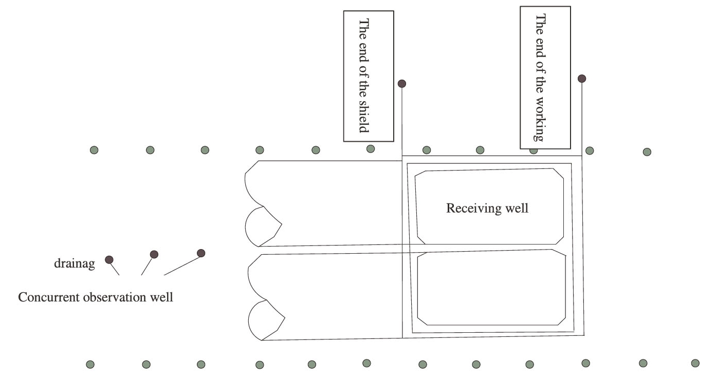
Fig.2.5 The layout of drainage wells at the end of Nanjing Yangtze River Tunnel
At present,the commonly used well points are light well point,spray well point,electroosmotic well point,deep well point,etc.The specific method should be selected according to the permeability coefficient of soil,the depth of required water level reduction,engineering characteristics,equipment conditions and field construction conditions,as shown in Table 2.1.
Scope of application of drainage method:to prevent mud gushing or sand flowing in shield well construction.During the construction of shield tunnel,the soil at the excavation face is stabilized,and the mud leakage and water leakage at the shield tail are also prevented.The well points are arranged on both sides of the shield axis.Well point precipitation is particularly suitable for the construction of shield tunnels.In the use of building-intensive areas,its impact on surrounding buildings must be fully considered.
2.2.1.1 Light Well Point Drainage
Light well point drainage is now widely used in various projects,especially in coastal or high water level soft soil foundation.The use of light well point precipitation has good economic and technical effects,as shown in Fig.2.6.
1)Characteristics
The light well points are flexible in layout,easy to use,fast in construction,and high in precipitation efficiency.Even if individual well pipes are damaged,the whole system will not be affected,and the project can adapt to the change of construction conditions.Light well point equipment can be used repeatedly with low construction cost.
Table 2.1 Common well point precipitation methods
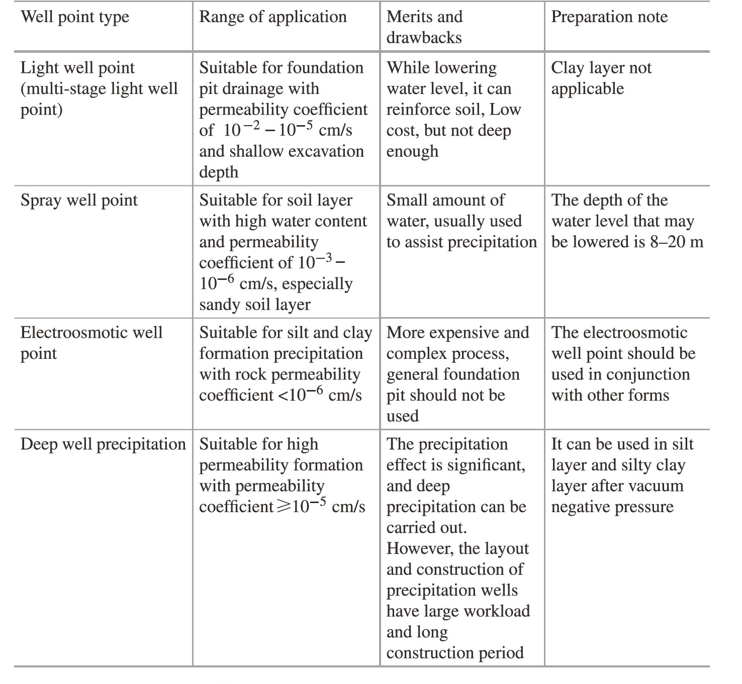
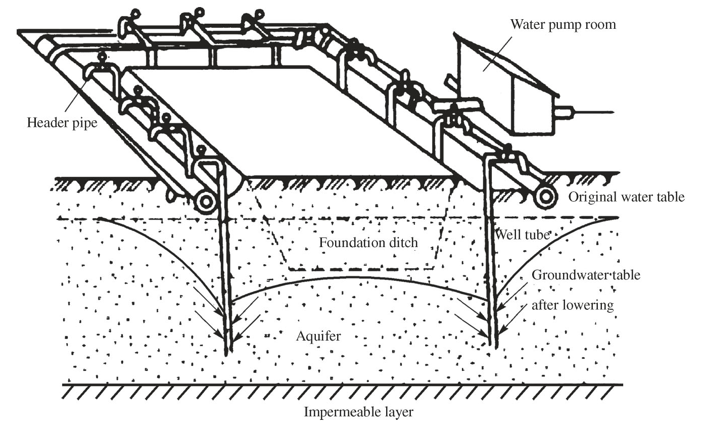
Fig.2.6 Schematic diagram of light well point drainage
2)Scope of application
Because the pumping unit of the light well is placed on the ground and the vacuum is produced on the ground,the precipitation depth is limited by the vacuum suction range.The buried depth of the first light well point drainage well is generally about 6 m.The soil layers suitable for light well sites are silty sand,sandy silt and clayey silt.
3)Process principle
Light well point drainage is that the well point branch pipe with filter is drilled into the soil layer,and sand is filled around the branch pipe,and then all the well point branches are connected to the pumping unit on the ground through the horizontal water collection pipe,and the groundwater is sucked to the ground by the pumping unit and excluded.
4)Technological process
Light well point drainage technological process as shown in Fig.2.7.
2.2.1.2 Spray Well Point Drainage
1)Characteristics
The spray well point can effectively reduce the groundwater level of 8-20 m.Spray well point can meet the requirements of deep drainage during caisson and shield construction.The effect of spray well point precipitation is significant,and it has good economic effect in weak permeability strata,which has been widely used in underground deep foundation construction.(https://www.daowen.com)
2)Scope of application
Because the spray well point uses high pressure water(or compressed air,water vapor)as the working medium,the vacuum is produced by jetting in the injector under the well tube,and the groundwater is inhaled into the well tube and the working medium,and then the groundwater is sent to the ground by the pressure of the working medium.Therefore,the water absorption capacity is large,and the precipitation depth depends on the pressure of the working medium and is not limited by the vacuum dust absorption.The precipitation depth can be increased by increasing the pressure of working medium.So the depth of primary drainage in general spray well point can reach about 20 m.The suitable soil layers for injection wells are silty sand,sandy silt,clayey silt and silty clay.
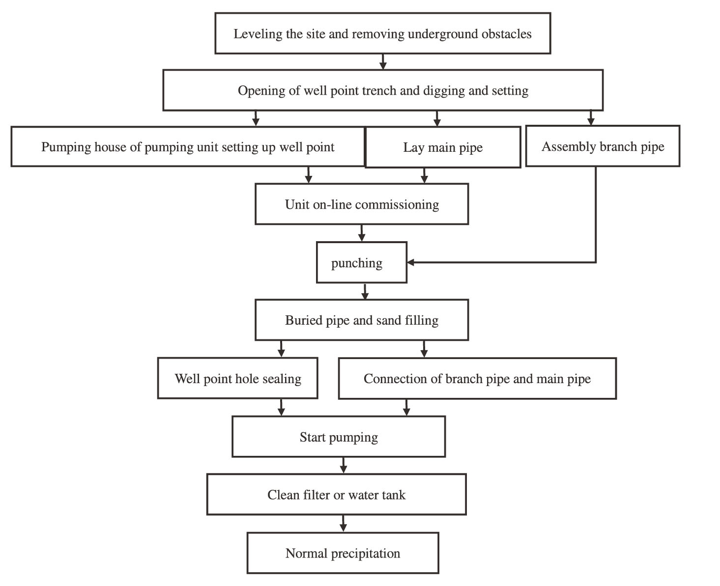
Fig.2.7 Process flow of light well point drainage
3)Process principle
Spray well point drainage is to drill holes in the soil around the required precipitation position,put the double-layer well pipe with filter and ejector into it,fill sand around the well pipe,and connect it with the inlet and outlet main pipe,so that the highpressure working water output by the unit(generally high-pressure water pump)enters the well pipe ejector.The vacuum produced by the ejector is inhaled by the filter and mixed with the working water into the water tank,and then the excess water is overflowed by the water tank to achieve the purpose of removing groundwater.
4)Technological process
The technological process of spray well point drainage is shown in Fig.2.8.
5)Spray well point equipment.
Spray well point equipment mainly includes:high pressure centrifugal pump,well point pipe,filter pipe,circulating water tank,inlet pipe,drainage pipe and low pressure centrifugal pump.
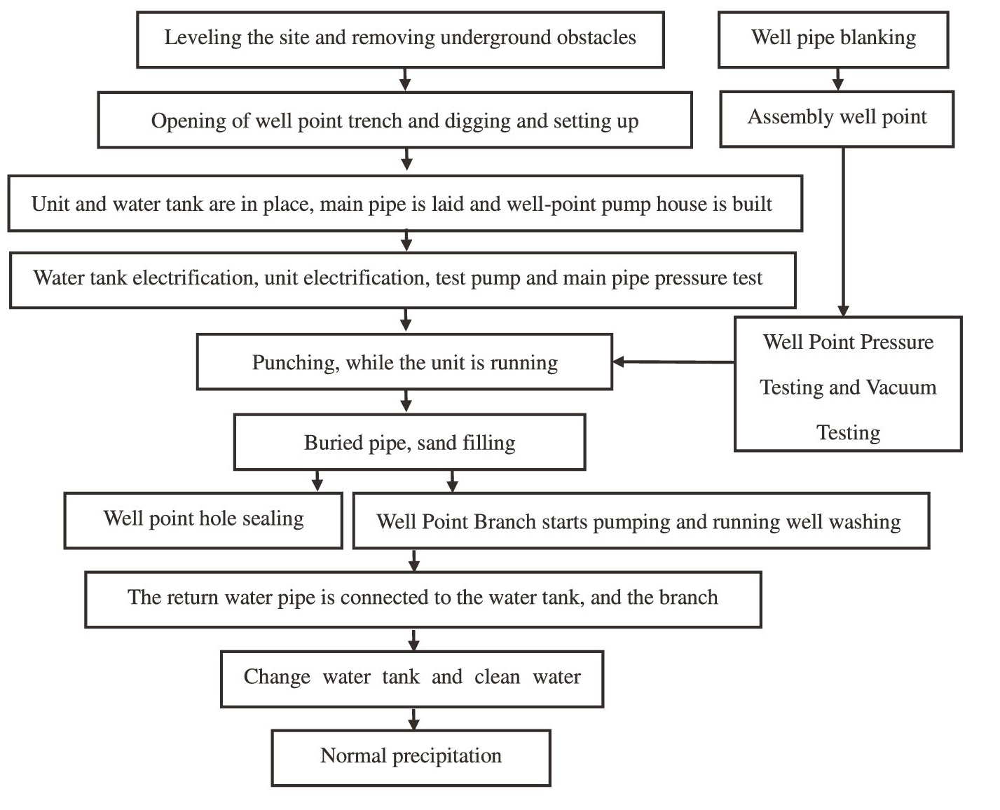
Fig.2.8 Technological process of spray well point drainage
Well point pipe includes:inner pipe,outer pipe,jet water heater and filter pipe.Spray water lift is composed of inlet window,nozzle,mixing chamber(also known as throat),diffusion tube,etc.
The spray well point spacing is generally 2-3 m,and the well placement is similar to the light well,but the punching diameter should be 40-60 cm.
2.2.1.3 Electroosmotic Well Point Drainage
In saturated clay soil,it is difficult to discharge groundwater by general precipitation method because of poor water permeability(permeability coefficient<0.1 m/d),so it is necessary to discharge groundwater by electroosmosis well point.
The free water flowing in the soil layer under the action of gravity can be extracted from the well points except the electroosmotic well point.However,a large number of bonded water in the cohesive soil will not move under the action of gravity,so the free water is in a state of segmentation in the clay.Its flow is hindered by the bonded water,so the flow is also very slow.If two electrodes are inserted in saturated clay and direct current is applied,the water in the soil at the anode will move to the cathode,and the fine particles in the soil will move to the anode.The former is called electroosmotic phenomenon,and the latter is called electrophoresis phenomenon,as shown in Fig.2.9.
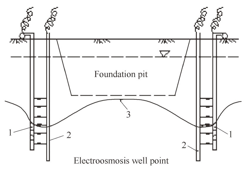
Fig.2.9 Schematic diagram of drainage at electroosmotic well point.1—Well point pipe;2—Metal rod;3—Underground water fall curve
The electroosmotic well point is to reduce the groundwater level in the clay layer by electroosmotic principle.Generally,the light well point is used as the cathode,and the corresponding anode is inserted next to it.The anode can be reinforced,with a diameter of 20 mm and a spacing of 0.8-1 m.Cathode is 20-40 cm deeper than anode,using no more than 60 V direct current as electroosmosis well point voltage,common is using welding machine instead of transformer(voltage 40 V,current 600 A).
2.2.1.4 Deep Well Point Drainage
The biggest feature of the deep well pump is to put the pump in the well pipe and rely on the head of the pump to send the deep groundwater to the ground,so the water level can be reduced to 30-40 m or more.Deep well point is one pump per well,working independently.There are two types of deep well pumps.
(1)The motor in the ground deep well pump,mainly consists of three parts:pump body is vertical multistage centrifugal pump,water pipe.The bottom is a filter.Others include water pipe,motor drill,transmission shaft and filter head.
(2)The shape and structure of deep well submersible pump are similar to those of common submersible pumps.It is mainly a submerged deep pump with large head and good insulation.