7.2.3 Selection of Shield Construction Parameters ...
Taking Nanjing Yangtze River Tunnel Project as an example,this section introduces the selection of relevant tunneling parameters and numerical simulation calculation during the construction of the middle channel section.
The distribution of strata in the middle channel section of Nanjing Yangtze River Tunnel Project is shown in Fig.7.1.The specific geological conditions of the main strata under shield tunneling are as follows.
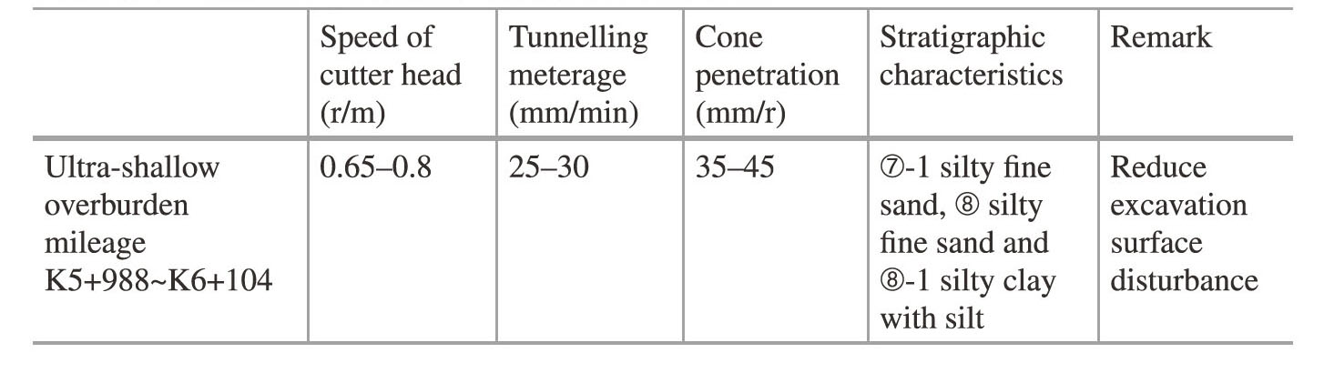
⑦-1 layer of silty sand:gray-greenish-grey,saturated,slightly dense-medium dense,rapid rocking reaction,microstratigraphy,containing mica debris,locally intercalated with silty soil thin layer,1-3 mm thick,uneven.
⑧Layered silty sand:grayish,saturated,medium dense,locally dense,poor particle gradation,and the main mineral components are quartz,feldspar,mica,etc.,uneven and widely distributed.
⑨Layered silty sand:blue-gray—blue-gray,saturated,dense,rapid rocking reaction,poor particle gradation.The main mineral components are quartz,feldspar,mica,and partially entrained with silt and silty clay.Couple gravel,particle size 2-15 mm.Mainly distributed in the north,south,missing in the middle.
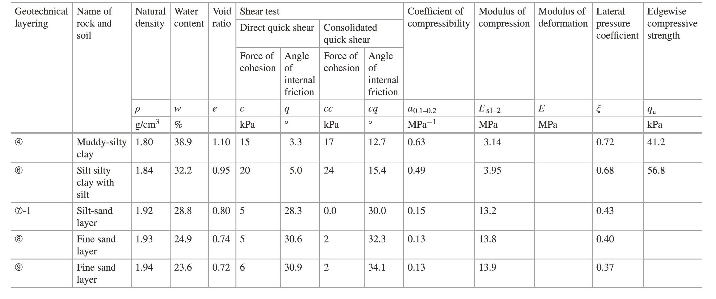
Basic physical parameters of three formations are shown in Table 7.1.
7.2.3.1 Parameter Selection and Construction Control Measures
1)Mud pressure
Table 7.1 Table of physical parameters for shield tunneling through main strata in middle channel section of Yangtze River
Since the slope section with a slope of 30°appears after the mileage K6+96.2,there is a slope effect,the slurry pressure of the whole shallow overburden section is set to be divided into two parts:the conventional pressure before section 3 and the slope pressure after section 3.
Conventional incision water pressure setting:Pconventional=(Pa+P0)/2+0.2.
Slope section incision pressure setting:Pslope=(Pa+P0)/2+Pfix.
Among them,Pa is the main dynamic earth pressure,P0is the static earth pressure,and 0.35 bar is selected for the revision.The water depth in the calculation of slurry pressure is based on the actual water level of the Yangtze River during construction,and is adjusted according to the tidal water level of the Yangtze River when the shield passes through the shallow overburden.The mud pressure should be strictly controlled according to the technical bottom,and the deviation is between±0.1 bar.
2)Velocity of slurry pipe
According to the experience,the slurry density of the discharge pipe is 1.30-1.40 t/m3,and the dry density of the gravel sand layer is 1.72 t/m3.According to the formula of the minimum limit flow rate of Durangde,the minimum sludge discharge of the discharge pipe in the gravel sand layer is Q=1731 m3/h.Considering the matching between the inlet and outlet slurry volume and the tunneling speed,the inlet slurry volume of fine sand and gravel sand layer is set to 1900 m3/h,and the outlet slurry volume is set to about 2150 m3/h.
3)Driving speed and cutter speed
Driving speed and cutter head speed are set according to geological conditions and construction experience,as shown in Table 7.2.
4)Grouting behind segment wall
(1)Selection of slurry type.In the early slurry shield tunnels,the synchronous grouting is generally used with double slurry.In the recent large slurry shield tunnels,the single slurry has replaced the double slurry,and has been successfully applied,such as the Shangzhong Road Cross River Tunnel and the Shanghai Yangtze River Tunnel.Compared with double slurry,single slurry has the following characteristics:
①Wide material,no pollution and low price.
Table 7.2 Excavation parameters of shallow overburden
②Good pumping,slurry filling effect,low grouting.However,it is difficult to control the setting time of the double-liquid slurry,which is easy to cause pipe plugging and slurry filling inaccuracy.Moreover,the slurry is easy to split the soil layer,resulting in the slurry being pressed into the soil with previous gaps,resulting in the grouting amount far exceeding the theoretical value,and the disturbance to the soil is large,which is easy to cause surface subsidence.
③When the yield strength of the slurry exceeds 800 Pa for 20 h,the slurry has good resistance to tunnel floating,and the dislocation between the tunnel rings is generally within 0-6 mm.The strength of double slurry solid is uneven,and the tunnel settlement and floating are large during construction.
④The combination of bentonite and admixture not only reduces the water demand of slurry,but also makes the slurry have good slump retention ability.(https://www.daowen.com)
⑤It has the performance of effectively preventing the back channeling of slurry,not damaging the shield tail device,and not being diluted or dispersed by slurry and groundwater.The double slurry is vulnerable to the dilution and penetration of groundwater and slurry of shield front support,and the setting time and strength of slurry are difficult to control.
In summary,Nanjing Yangtze River tunnel synchronous grouting using single slurry.Considering that the single liquid slurry has a long initial setting time and good fluidity,it will have a negative impact on the settlement that needs to be quickly controlled during shield construction.Therefore,when passing through the section,if the settlement cannot be effectively controlled,the rapid grouting filling is carried out with the tested double liquid speed cement to stabilize the soil.
(2)Setting slurry parameters.According to the geological conditions,the particle gradation of fine sand layer in the shallow overburden section of the middle Yangtze River is poor,and the gravel sand layer filling is easy to be washed.In order to prevent shield tail slurry leakage,tunnel floating and stratum instability,it is necessary to strengthen the post-grouting control of segment wall to ensure the quality of synchronous slurry.The slurry density was set as 1.96 g/cm3,and the slurry slump was controlled at 18-22 cm.The grouting volume is controlled at 150%-200%of the theoretical void volume to ensure that the grouting behind the wall is dense and effective.At the same time,the grouting pressure is controlled to prevent the breakdown of the shallow soil layer.The grouting pressure is set to 95%-105%(fluctuation±0.1 bar,matching with the slurry pressure)of the slurry pressure at the position of the grouting pipe,and the pressure loss from the pump head to the outlet of the slurry pipe.
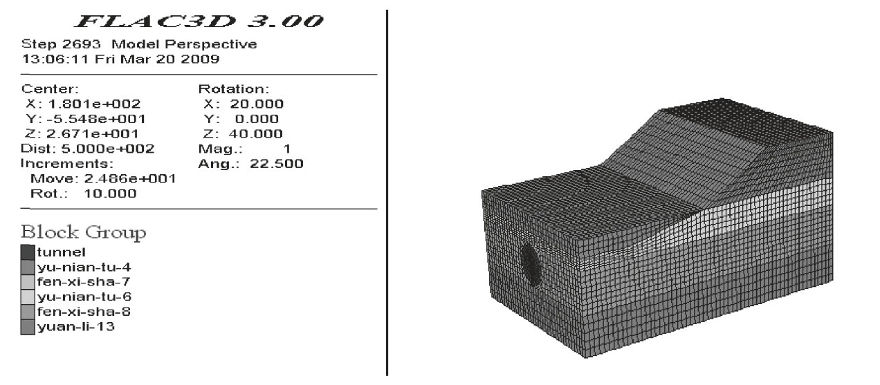
Fig.7.8 Topographic map of gully section when vertical and vertical scales are consistent
7.2.3.2 Numerical Simulation Analysis of Slurry Pressure Setting in Left-Line Tunnel Flushing Section
The static earth pressure and instability pressure of the shield incision with the minimum overburden mileage are simulated by numerical simulation.The numerical calculation results are compared with the calculation results of the classical formula,and finally a more reasonable set value of slurry pressure is obtained.
1)Model calculation range
The actual slope of the groove section is about 30°,and the geological longitudinal section is illusioned due to the inconsistent vertical and vertical ratios.The topographic conditions of the groove section are redrawn to obtain the topographic map of the groove section when the vertical and vertical ratios are consistent,and the numerical modeling is carried out accordingly.
As shown in Fig.7.8,the slope mileage is K6+098-K6+118.According to the actual construction situation,when the shield passes through the groove section,in order to ensure the safe passage of this section,the slurry pressure setting value in the slurry shield pressure cabin is constantly changing.The specific change process is as follows:from K6+090 to K6+098 and then to Pslope,from K6+115 to K6+118 and then to Pconventional.
2)Establishment of calculation model
The finite difference software FLAC3D is used to simulate the actual working conditions.The numerical model takes K6+000-K6+175 strata and tunnels for modeling analysis.The model takes the most unfavorable working conditions,and takes the minimum overburden mileage as the starting mileage of slope toe.The minimum overburden thickness is 11.3 m,and the water level elevation is 5 m.The model is shown in Fig.7.9.Fig.7.9a is a complete tunnel model.In order to shorten the calculation time,one-half model Fig.7.9b is used and inside the tunnel.The lining shell element is added,and the stress perpendicular to the excavation surface is applied on the excavation surface to simulate the slurry pressure of the shield slurry tank applied on the excavation surface.
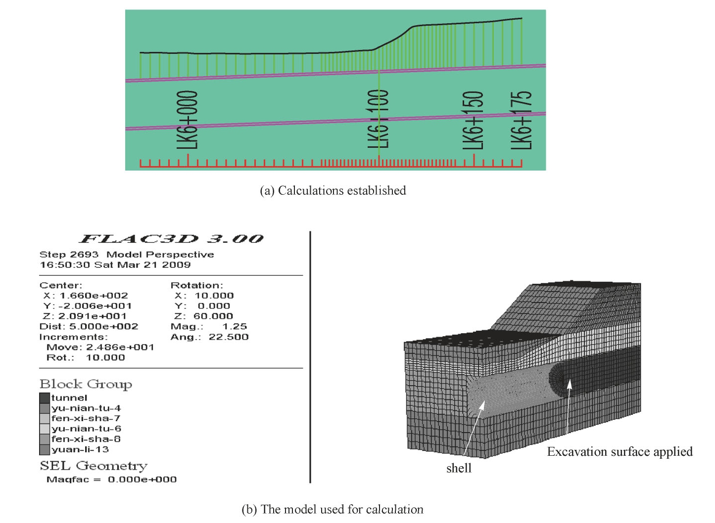
Fig.7.9 FLAC3D numerical simulation
3)Calculation and analysis of calculation results
(1)Calculation results.The formula and FLAC3D are used to calculate the pressure of the incision.The results are shown in Table 7.3.
(2)Analysis of calculation results.According to the calculation results obtained by the finite difference software FLAC3D,itis analyzed to obtain a more reasonable pressure value and guide the construction.The results are shown in Figs.7.10~7.12.
The actual values of active soil pressure and static soil pressure in the slope section should be greater than the formula calculation results,but the numerical solution of active soil pressure in the current calculation results is less than the formula solution,which is not desirable.The reason is that the software is difficult to simulate the slip failure of soil,and the horizontal displacement of soil has lost practical significance when instability occurs.
Table 7.3 Comparison of calculation results of incision pressure
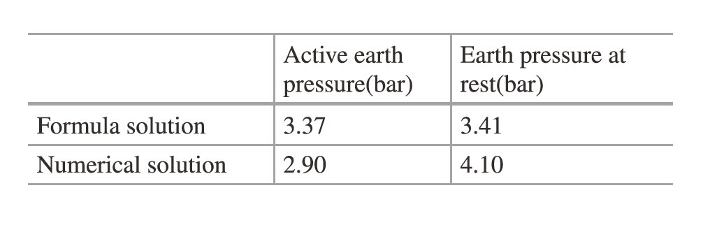
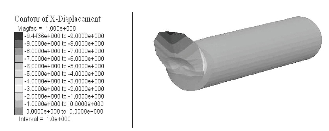
Fig.7.10 Horizontal displacement of excavation face at 2.9 bar incision pressure
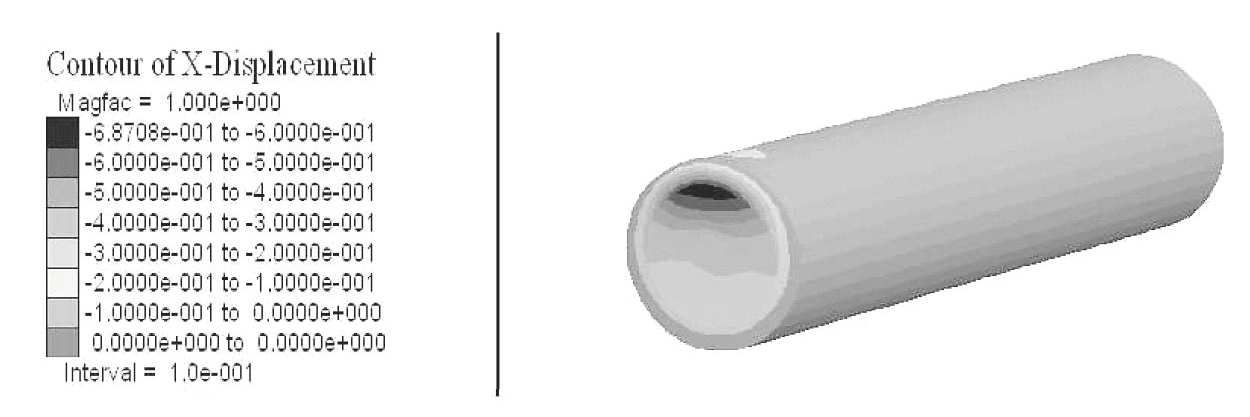
Fig.7.11 Horizontal displacement of excavation face at 3.0 bar incision pressure
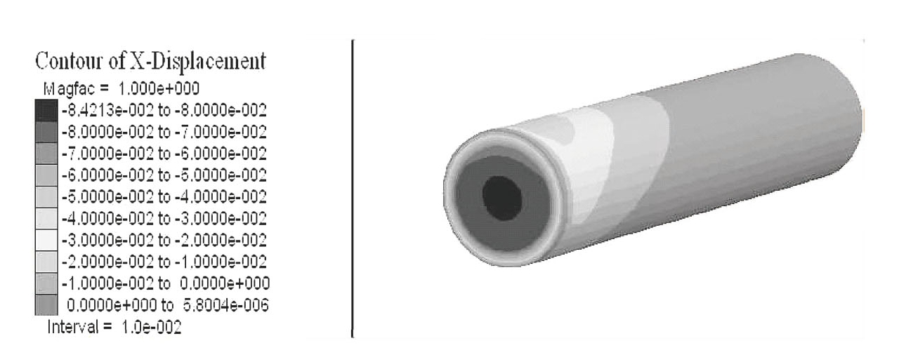
Fig.7.12 Horizontal displacement of excavation face at 3.4 bar incision pressure
Standard for numerical calculation of static earth pressure:when horizontal displacement of excavation face is almost zero,support pressure is static earth pressure.The numerical solution of static earth pressure is 4.1 bar,and the formula solution is 3.41 bar.The difference between them is about 0.7 bar.
Therefore,the recommended value ofPamendment can be initially taken as half of the difference between the numerical solution and the formula solution of the static earth pressure,Pamendment=0.35 bar,adjusted according to the surface subsidence or other monitoring feedback results when the actual pressure is set.