6.2.3 Shield Fault Diagnosis Technology and Applic...
In order to ensure the normal construction of shield tunneling,through the analysis of hydraulic oil and gear oil,without disassembly of equipment and without affecting the normal construction,the fault prediction of hydraulic system and main drive gear system is realized,which provides scientific basis for the maintenance of relevant departments.
6.2.3.1 Sampling
The oil sample is the main basis for oil analysis,and all fault information is integrated into it.Therefore,whether the oil extraction specification directly determines the monitoring conclusion of the equipment.
Table 6.12 P1.1B motor vibration time domain statistics
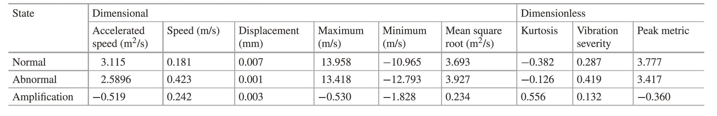
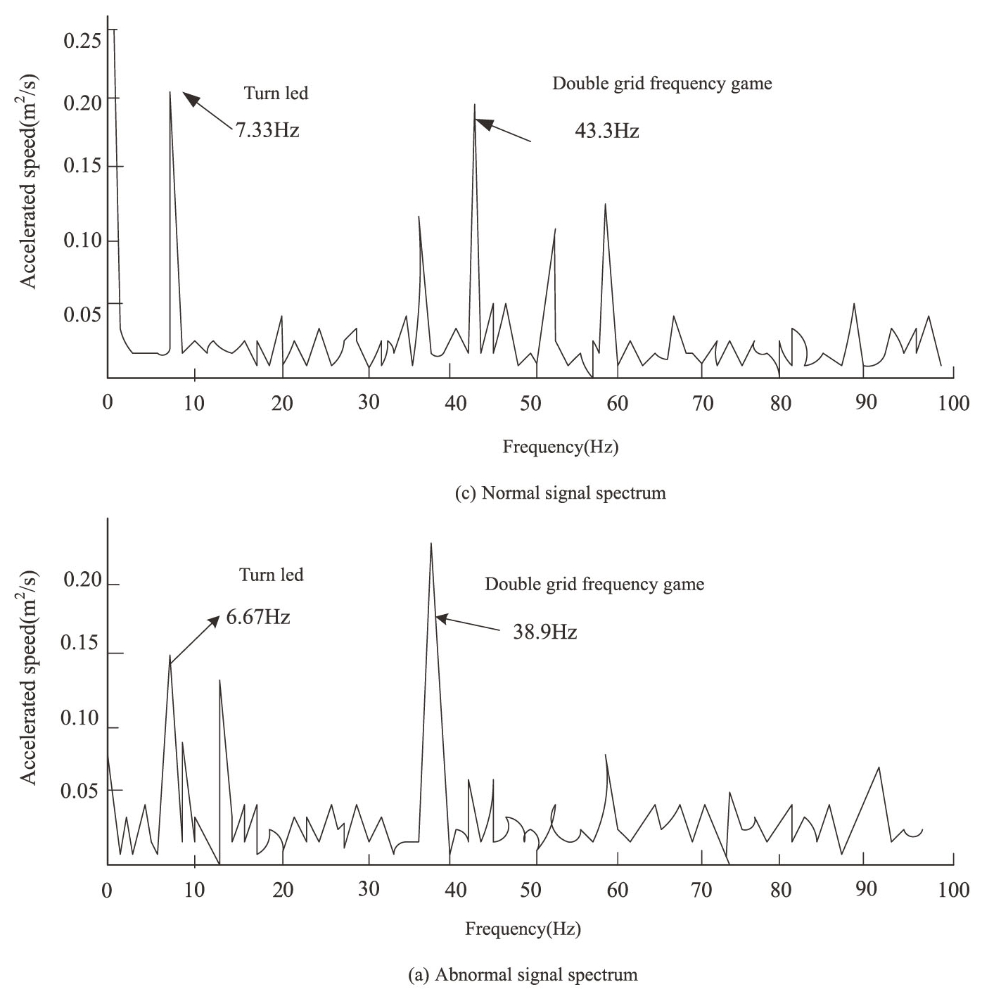
Fig.6.33 Spectrum of motor vibration
1)Sampling conditions
Abrasives and impurities entering the lubricating oil mostly exist in the form of organic compounds,colloidal suspensions and free particles,some hanging in the inner wall,some in the oil,and some deposited in the oil bottom when the lubricating oil is static.Therefore,the oil extraction must be in the shield tunneling state or just stop tunneling,to ensure that the abrasive particles in a just uniform suspension state.
2)The sampling location
Reasonable location should be selected after the hydraulic system and the friction pair of the main drive gear system and before the filter.
3)Sampling tools and sampling quantities
Use the special tools for sampling to take oil.The sample bottles and oil collection pipes are disposable and discarded after use.There are many items considering oil analysis,and the sampling amount is set to 200 mL each time.
4)Sampling cycle
The oil sampling period is one month.If the equipment has abnormal wear,the sampling period should be shortened as appropriate.The main drive gear ring and hydraulic system wear rate is relatively low,can be appropriately extended.
6.2.3.2 Oil Analysis
The main items of oil analysis include:kinematic viscosity,iron spectrum,moisture,pollution and spectral analysis,where spectral analysis requires outbound inspection.
1)Kinematic viscosity and moisture analysis
The detection standard of oil kinematic viscosity:the change rate at 40℃should not exceed 10%of the normal kinematic viscosity.If the viscosity is too low,it will cause lubrication failure and serious wear.Too high viscosity will make the oil temperature rise,resulting in oxidation of the lubricating surface,but also increase power consumption,resulting in energy waste.
Moisture detection standard:moisture content should be no more than 0.1%.Excessive moisture content can cause corrosion of sensitive parts and cause malfunctions.
2)Oil sample iron spectrum analysis
Ferrography is used to separate and detect abrasive particles and debris from lubricating oil samples(greases)by ferrography,so as to analyze and judge the wear type,wear degree and wear position of the surface of the machine moving pair.The direct reading ferrography technology is used to analyze the ferrography of oil samples.
(1)Working principle of direct reading type ferrography.
The wear debris was separated from the oil by a direct-reading ferrograph and deposited on the deposition tube according to the size for analysis by the tester.Magnetic field device is a high strength and high gradient magnetic field.Under the action of magnetic field,large particles first deposit,and small particles deposit with the oil flow to a distance.Photoelectric sensors installed in different locations read out the number of different sizes of abrasive particles.
(2)Direct reading type of ferromagnetic characteristic parameters.
①Large abrasive reading Dt.Dt is the first reading of the photoelectric sensor read by the direct reading spectrometer.It represents the relative concentration of large abrasive particles with a diameter greater than 5μm and is one of the main parameters for rating mechanical wear.
②Small abrasive readings Ds.Ds is also the original reading directly displayed by the direct reading spectrometer,representing the relative concentration of small abrasive particles(1-2 μm),can also reflect the iron content of the oil sample.
③Total wear amount Q.Q is the sum of the large abrasive particles and the small abrasive grain readings,Q=Dt+Ds.It reflects the relative amount of wear,and its rate of change reflects the rate of development of wear.(https://www.daowen.com)
④Wear intensity 1s.Ls is the product of total wear and wear severity,i.e.ls=(Dt+Ds)(Dt-Ds),which is related to the severity of wear.Under normal friction and wear conditions,the values of Dt and Ds are close.Only under abnormal wear conditions will the Dt value greatly exceed the Ds value.Therefore,the appearance of the 1s peak is a sign of an accident.
⑤Major abrasive percentages PLP.The PLP reaction large abrasive grains accounted for the specific gravity of the total amount of abrasive grains,PLP=[Dt/(Dt+Ds)]×100%.When the equipment is abnormally worn,the number of large abrasive grains will increase sharply,and the PLP value will increase significantly.Therefore,PLP is very sensitive to the monitoring of large abrasive grains.
⑥Abrasive concentration PLP.PLP=(Dt+Ds)/sample size,which represents the total amount of wear per ml of undiluted sample.The sharp increase in PLP marks the appearance of abnormal wear.
3)Iron spectrum abrasive grain characteristics
The wear process typically produces six basic types of abrasive particles,including combinations of ferromagnetic and non-ferromagnetic particles.
(1)Normal sliding particles.The normal sliding particles are the result of normal wear,and the abrasive particles from the shear mixing layer are thin flakes with smooth surface,the long axis size is 0.5-15μm,and the thickness is 0.15-1μm.
(2)Cutting abrasive grains.Cutting abrasive is the result of one surface penetrating another surface,there are two ways to produce this result.First,a relatively hard component may be misalignment or fracture,resulting in sharp edges penetrating into a soft surface.Secondly,the hard abrasive particles in the lubrication system stand out from the soft surface and pierce into another worn surface.If a system is growing large(50 μm long)abrasive particles,it indicates a component failure.
(3)Spherical abrasive grains.
Spherical abrasive particles.The diameter of spherical abrasive particles is about 3 pm,which has bright center and black band imaging characteristics under white light irradiation.Relative movement and rubbing are the characteristics of fatigue wear.
(4)Severe sliding.There are parallel stripes on the surface of severely worn particles,and these stripes are parallel to each other and parallel to the long axis of particles,which is the identification feature.They are generally greater than 15μm in length and 5-30 μm in thickness.Severe sliding particles sometimes show tempered color,which may change the appearance of particles after heat treatment.
(5)Bearing abrasive grains.These unique particle types are related to the fatigue of rolling bearings.The fatigue debris particles originate from the delamination when the metal surface is dented or cracks expand.During the micro-cracking process,these particles reach the maximum size of 100μm.The fatigue crack is generally flat,and the main length-thickness ratio is 10∶1.The surface is flat and the circumference is random irregular.
(6)Gear wear.Gears involve two types of wear:the fatigue particles of pitch circle are derived from the gear pitch circle,which are very similar to the fatigue particles of rolling bearings.They generally have flat surfaces and are usually irregular shapes.Depending on the design of the gear,the main size and thickness ratio of the particles are between 4∶1 and 10∶1.The short fat particles are produced by the tensile force on the surface of the gear,so that the fatigue fracture extends into the gear teeth before cracking.
4)Spectral analysis characteristic parameters
The characteristic parameter of spectral analysis is the concentration of various elements in oil.Its quantitative unit is mg/L,commonly known as PPM.
After a large number of tests,certain rules were found from the increase and decrease of element concentration.Wear metal components are:iron,lead,copper,tin,aluminum,nickel,silver,molybdenum,magnesium,zinc,titanium,tungsten,antimony,vanadium,etc.The pollutants are mainly composed of silicon,boron,sodium and potassium.Oil additives are mainly composed of copper,magnesium,calcium barium,zinc,molybdenum,antimony,silicon,boron and phosphorus.
6.2.3.3 Engineering Application
From September 2009 to July 2010,the lubrication and wear status of the main bearing of the left shield in a project department was tracked and monitored by the Equipment Condition Monitoring Institute of Guangzhou Institute of Mechanical Research using oil analysis technology.The project department adopted slurry air cushion balance shield with excavation diameter of 11.92 m.The main bearing lubrication system of the shield adopts BP Energol GR-XP 680 gear oil and adopts centralized lubrication mode.
When sampling and analyzing on November 23,2009,the viscosity of oil sample increased significantly,far beyond the allowable range of viscosity of lubricating oil in use.Wear metal elements Fe,Cu content beyond the normal range,as shown in Fig.6.34.Elements Mo,Ca,Na content increased significantly,as shown in Fig.6.35.According to the results of oil monitoring and analysis,it is preliminarily judged that the oil is polluted by external contamination,which causes viscosity,Mo,Ca content increased sharply.
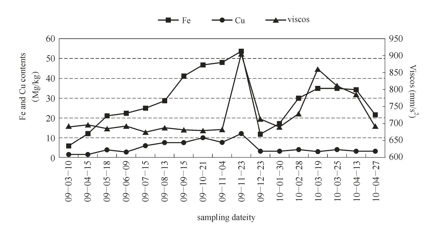
Fig.6.34 The variation trend of Fe and Cu content and viscosity at 40℃
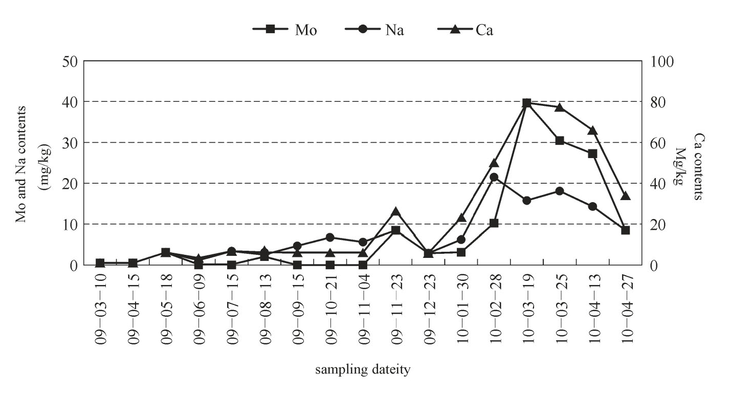
Fig.6.35 Variation trend of Mo,Ca and Na contents
In order to determine the source of pollution,the possible external pollution sources such as groundwater,slurry water and slag slurry in the construction site were sampled and analyzed,and the BP Energol,GR2XP680 new oil,HBW new and EP2 new grease were detected and analyzed.The results are shown in Tables 6.13 and 6.14.
Table 6.13 Spectral analysis of new oil and pollutants
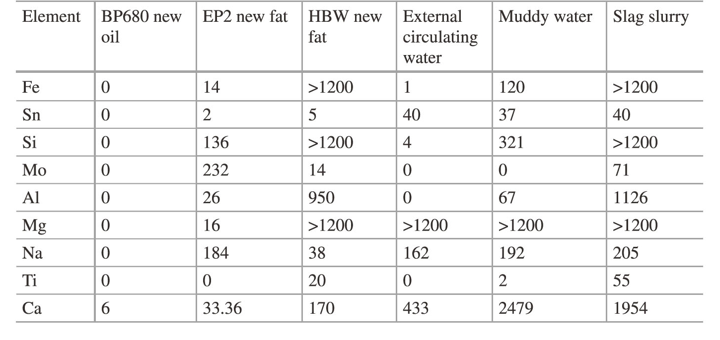
Table 6.14 Periphery analysis of solid particles of new oil and pollutants
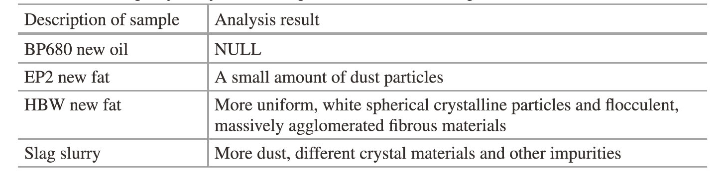
Combined with the analysis in Tables 6.13 and 6.14,the main sources of Mo and Ca are EP2 grease,and Na mainly occurs in slag slurry,slurry water and EP2 grease.However,the content of Mg in slag slurry and slurry water is very high,and no increase in Mg content is found in this monitoring.Therefore,it can be inferred that the main reason for the increase in the viscosity of the bearing gear oil and the content of Mo,Na and Ca is the pollution ofEP2 grease.After determining the source of pollution,the lubrication system of the main bearing was oil changed,and the oil tracking and monitoring of the unit were strengthened.According to the analysis results,corresponding measures were taken to meet the needs of normal lubrication of the bearing so that the shield can operate safely.