3.3.2 Model Test of Slurry Shield Excavation Mud S...
Taking Nanjing Yangtze River Tunnel as an example,this section introduces the model test and split failure process of slurry shield excavation.
Fig.3.6 shows the diagram of the shield model developed by ourselves.The proportion and strength of artificial gypsum clay used are shown in Table 3.2.The thickness of the overburden is 1.75D(D is the outer diameter of the shield).The unconfined compressive strength of soil layer is determined by adjusting the proportion of water,and the bentonite with 10%slurry is mixed.In order to observe the split surface,the mud water is colored red.The viscosity of slurry is 25-29 s.The test is carried out in two forms:one is in the case of upper load to simulate the large overburden,the other is the absence of upper load to simulate the thinner overburden.The shield modeling machine is driven by 1 mm/min and splits the formation with a fixed rate of slurry pressure(slurry eruption).The test is also carried out after driving 20 cm,and the formation is split and destroyed at a fixed rate of slurry pressure.
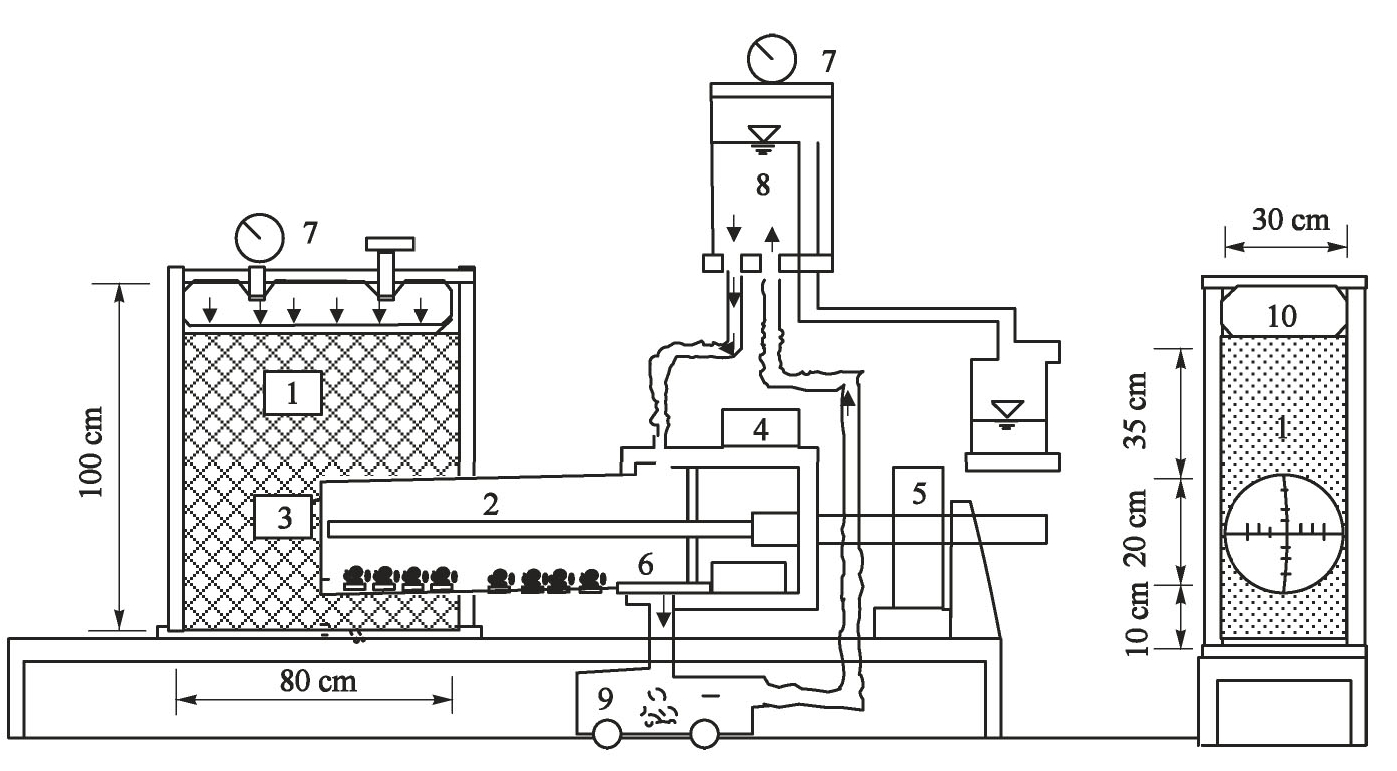
Fig.3.6 Shield model test device.1-Soil trough;2-tool;3-cutter head;4-cutter head motor;5-roadheader motor;6-drain;7-pressure gauge;8-mud tank;9-drain tank;10-upper load
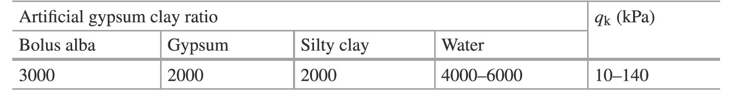
Table 3.2 Proportion and strength of artificial gypsum clay in soil trough
1)Splitting direction and width
Fig.3.7 shows the split condition of the upper load under the condition of 10 kPa.The split is radial pattern,it occurs on the vertical and parallel planes directly intersecting with the horizontal axis of the shield.In the case of upper load,the difference between lead straight earth pressure σ1 and lateral pressure σ3(σ1-σ3)is larger,and the split should occur on the surface perpendicular to the minimum principal stress σ3 in the horizontal direction,and the difference between the lead straight earth pressure and the lateral pressure is larger than that of the lateral pressure,and the split should occur on the surface perpendicular to the minimum principal stress in the horizontal direction.This is the same as the results of indoor split triaxial test,that is,the split occurs on a plane perpendicular toσ3.Fig.3.8 shows the split condition without upper load.
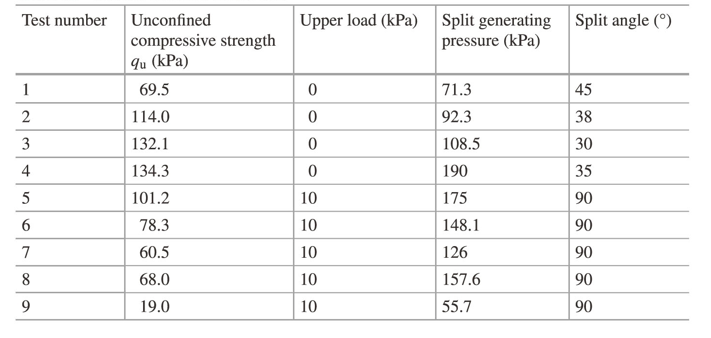
Splitting occurs obliquely upward from the cutting surface.In the case of no upper load,it can almost be considered that σ1=σ3,and the splitting occurs at any angle from the vertical direction to the horizontal direction.Therefore,without upper load,the split extends obliquely towards the only free surface,the ground surface.The angle of oblique upward cracking,as shown in Fig.3.9,is 30°-45°in various cases.Table 3.3 is the results of shield model test.
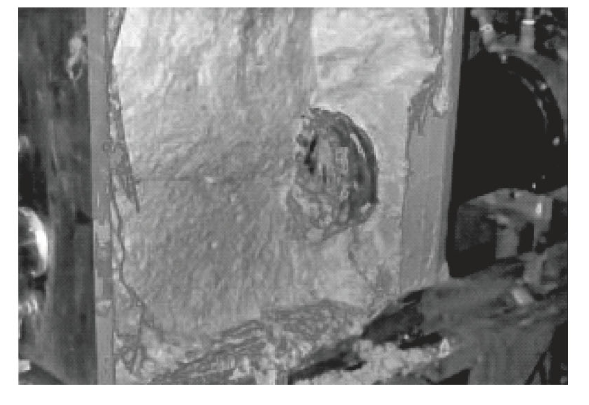
Fig.3.7 Split condition of upper load
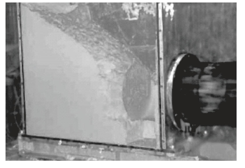
Fig.3.8 Split condition without upper load
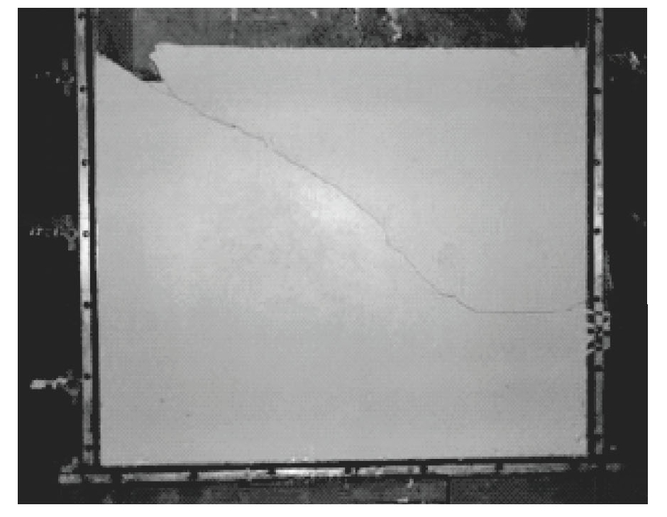
Fig.3.9 The split width of the second test
Table 3.3 Results of shield model test
Splitting occurs from occurrence to eruption,with each test taking approximately 2 s.In addition,the split width is 2.10-2.90 mm,with an average of 2.58 mm,as shown in Fig.3.9.
2)Splitting process of shield excavation face
Fig.3.10 is the result of the 9th test of slurry pressure and shield propulsion distance.After the test,the soil layer passed by the shield model machine was excavated.The observation results showed that there was no abnormality in section A in the figure,and the cracks before splitting were found in section B,as shown in Fig.3.11(since the colored dye is added to the slurry,the cracks can be clearly identified).These cracks are all radially extended from the wall,and the closer the splitting depth is to the slurry eruption,the deeper the splitting depth is.It can also be seen from Fig.3.10 that the mud pressure when cracks occur is much smaller than the mud eruption pressure(splitting).Fig.3.11 shows the crack spacing and shield cutter.(https://www.daowen.com)
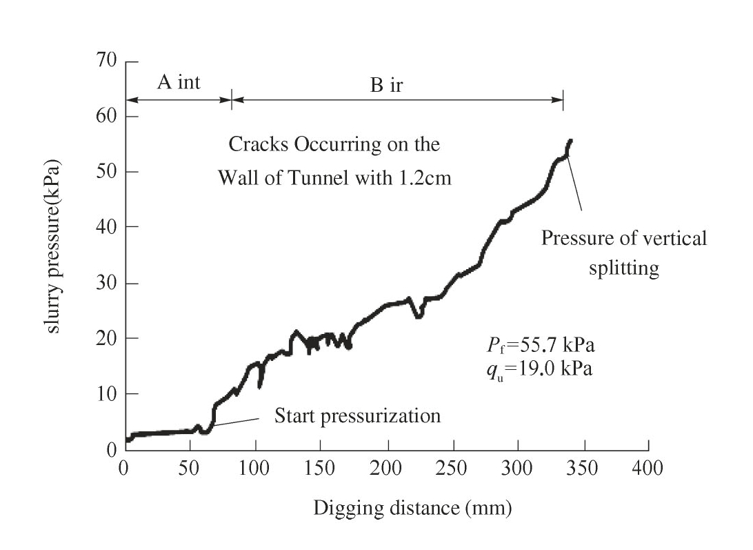
Fig.3.10 During the 9th test excavation process
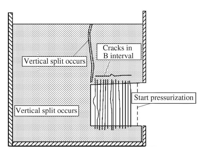
Fig.3.11 Crack and split condition of cracks and splits
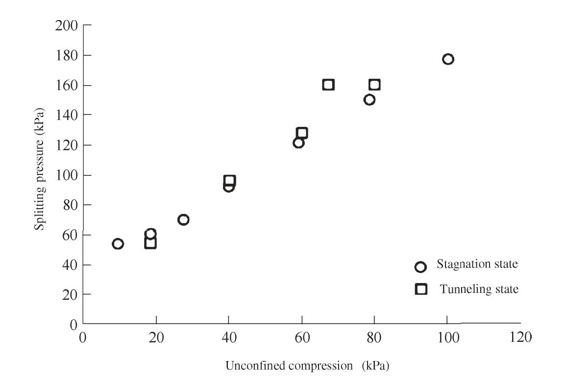
Fig.3.12 Influence of heading state on split pressure
The distance from the front end to the front end of the shield shell is almost equal,about 1.2 cm.When the actual slurry pressure is less than the slurry eruption pressure,the cracks also occur,but the length is very small,about 2 mm.At this time,the shield continues to dig 1.2 cm,the cracks have been blocked by the shield shell,slurry pressure can no longer act on the occurrence of cracks.The new excavation surface produces new cracks,so the cracks follow the ring.Fig.3.12 shows the effect of the tunneling state on the pressure of the split.
It can be seen from Fig.3.12 that under the condition that the unconfined compressive strength of the soil layer is equal,the pressure of the split in the shield tunneling and stopping state is almost equal.
3)Split occurrence time and extension speed
From the beginning of reaching the splitting pressure to the time of splitting occurrence of mud eruption,the time of splitting occurrence can be counted by videotape for about 2 s,and the preliminary calculation of the splitting extension speed is 20-30 cm/s.This split extension velocity is the key to the occurrence of slurry eruption in actual shield excavation.If within a certain period of time,the split extends to the ground and causes slurry eruptions,it will lead to major accidents,which may usually occur when the overburden is thin or shut down for a long time.Generally speaking,the split extension velocity is related to the area of the split orifice and the total length of the split front,which can be expressed as the following formula.
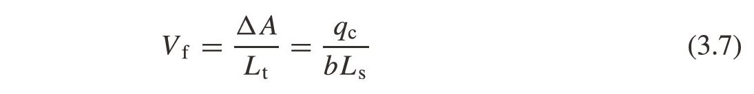
Vf—Split extension speed;
ΔA—Increase in area per unit time of split front end;
Lt—The circumference of the split orifice;
qc—The flow rate of mud water extended by splitting is directly proportional to the inflow area of mud water at the crack occurrence of the excavated surface;
b—Split width.