2.2.3 Scope of Soil Reinforcement
In this section,taking the deep mixing pile construction method as an example,the method to determine the range of foundation reinforcement area is described in detail.Table 2.3 and Figs.2.13,2.14 and 2.15 are the detailed forms of the three construction methods of deep mixing pile.
1)Reinforcement thickness
The opening part of the strengthened entity is regarded as a freely supported disc.Based on the checking calculation of the stress failure of the simply supported beam,the thickness which can resist the failure of the external force(active earth pressure+water pressure)on the back of the beam is calculated(Fig.2.16).
Table 2.3 Detailed forms of three construction methods of deep mixing pile
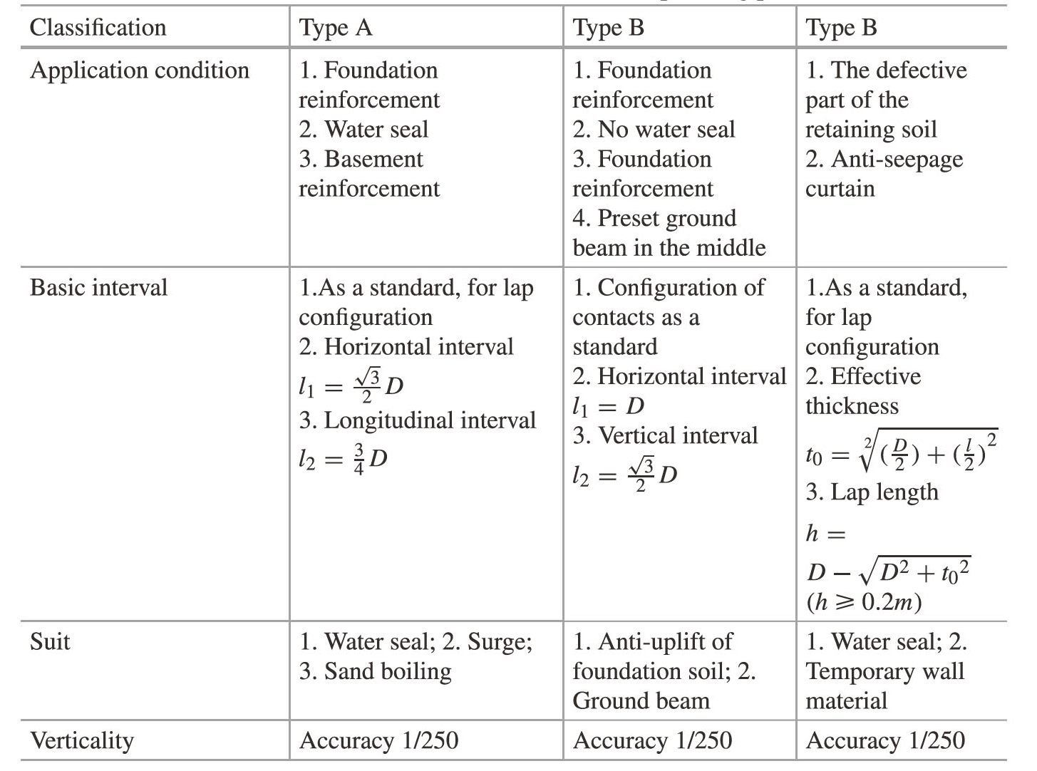
Note D-Effective diameter of pile;Z-Pile depth
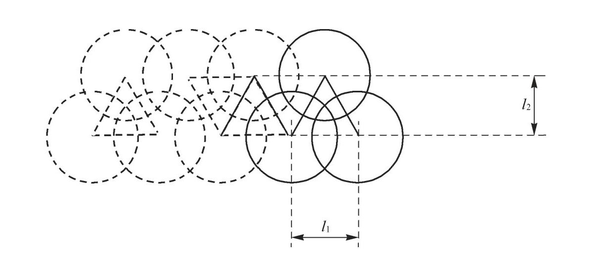
Fig.2.13 Type A foundation reinforcement
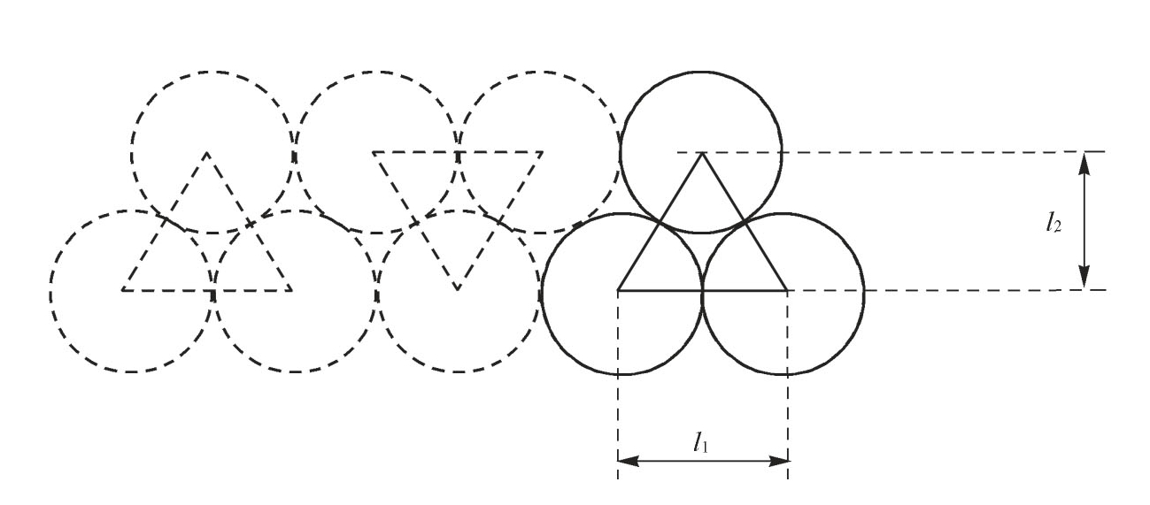
Fig.2.14 Type B foundation reinforcement
Fig.2.15 Type C foundation reinforcement
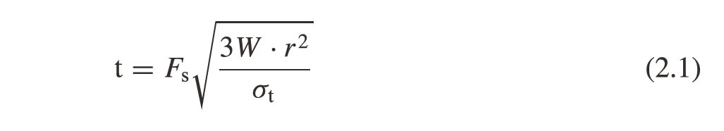
t—Reinforcement thickness(m);
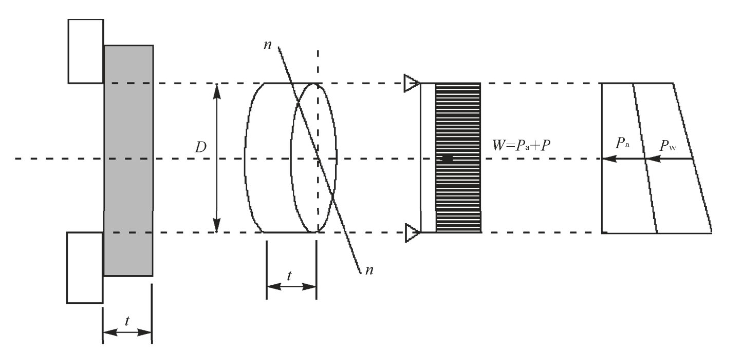
Fig.2.16 Calculation model of reinforcement thickness
Fs—The safety factor is 1.2 in soil mechanics and 2.65 in non-seismic inspection of concrete structure;
W—External force(mainly active earth pressure and water pressure)(kN/m2);
r—Shield excavation radius(m);
σt—The bending tensile strength of reinforced surrounding rock(kN/m2).
2)Reinforcement range
(1)Thickness required for upper part.
The reinforcement thickness of the upper part of the shield is studied by using the method of deducing the additional stress generated by the surrounding when the tunnel is excavated.
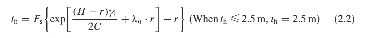
H—Depth to the center of the tunnel(m);
r—Shield open outer radius(m);
γt—The unit volume weight of surrounding rock after reinforcement(kN/m3);
C—Cohesion of surrounding Rock after reinforcement(kPa);
Fs—The safety factor is 1.2 in soil mechanics and 2.65 in concrete structure.
The upper reinforcement range is shown in Fig.2.17.
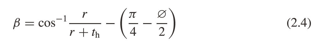
(2)Thickness required for lateral part.
The lateral part needs thickness to be the intersection range between the required thickness and the collapse angle(θ=π/4+Ø/2)obtained from the upper part(Fig.2.18).
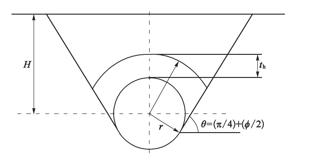
Fig.2.17 Upper reinforcement range model
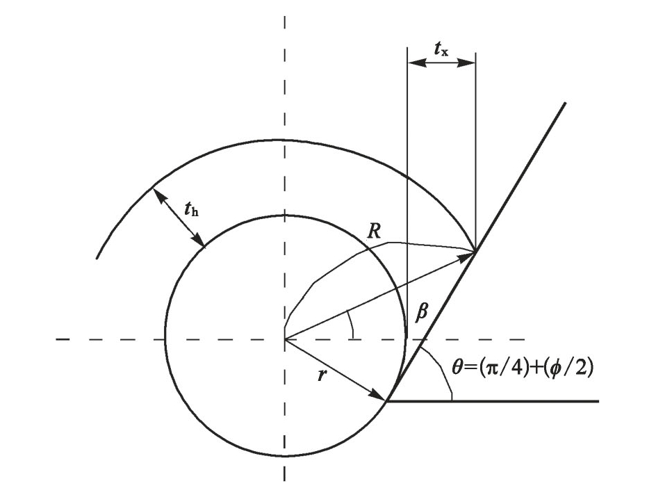
Fig.2.18 Side reinforcement range model
(Whentx≤2.0m,tx=2.0m)
r—Shield opening radius(m);
th—Upper reinforcement thickness(m);
Ø—The internal friction angle of surrounding rock;
tx—Side reinforcement thickness(m).
(3)Thickness required for bottom part.Consider water seal to ensure minimum thickness.
To sum up,considering the actual value so far,the minimum thickness in the reinforcement range is 2.5 m in the upper part,2.0 m in the side part and 1.5 m in the lower part as the standard value.Among them,the thickness of the lower part should be more than 60%of the upper thickness.