6.2.2 Shield State Monitoring and Fault Diagnosis ...
In shield construction,in order to facilitate operators to grasp the real-time status of the whole machine,the shield generally integrates a set of complex monitoring systems,and sometimes thousands of monitoring points,including propulsion system,assembly system,hydraulic system,grouting system,slurry system and lubrication system.These monitoring parameters are generally set the alarm threshold,such as the filter pressure differential alarm,sewage tank level alarm,and most of the parameters are simply feedback,display,by the operator with experience to determine its state.It is difficult for some key parts to judge their health status and make early prediction only by these feedback parameters.Such as the detection of hydraulic pump,shield only feedback its output pressure,only from the pressure observation,can not accurately determine its state,especially in the early stage of the fault.Therefore,it is necessary to develop a set of precision detection instruments to make up for the deficiency of the shield self-monitoring system.This section introduces a shield state detection and fault diagnosis technology based on virtual instrument technology combined with Nanjing Yangtze River Tunnel project.
6.2.2.1 Virtual Instrument Technology
The concept of virtual instrument was first proposed by National Instruments Corporation in 1986.The so-called virtual instrument(Ⅵ)combines the existing mainstream computer technology with flexible and easy-to-use software hardware to establish a powerful,flexible and changeable computer-based test measurement and control system,that is,to realize the function of traditional hardware with software.
The introduction of virtual instrument technology into the development of the system,not only saves the cost,but also greatly reduces the system development cycle,hardware and software system development time is less than two months.Through the modular management mode,the upgrade of the detection system is more flexible,which is convenient for the integration of new functions in the future.
6.2.2.2 Overall System Design
1)Test object
Carry out state detection,first determine the detection object.The structure of shield is complex,the probability of failure in each part is different,and the influence on the construction is different.Therefore,the system analysis of each part is carried out before determining the detection object,and the components with high risk,large fault loss or difficult repair after damage are selected as the key detection objects of this system.Vibration detection technology is most suitable for rotating equipment detection,and the key parts affecting shield tunneling are rotating parts,such as cutterhead drive system,propulsion system,slurry circulation system,etc.These components can be classified into four categories,namely motor,gearbox,hydraulic pump and bearing.The statistics of monitoring objects are shown in Table 6.8.
2)Measuring point selection
The quality of the measurement point determines the quality of the acquisition signal,so you need to do this step carefully.The selection of screening and measuring points follows the following five principles:
Table 6.8 Vibration detection object of shield
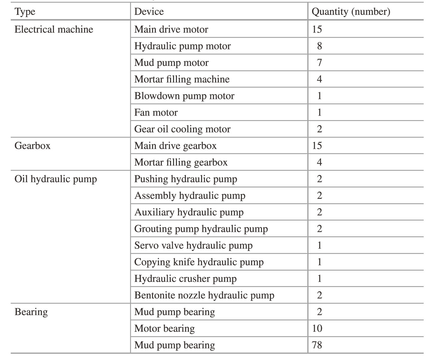
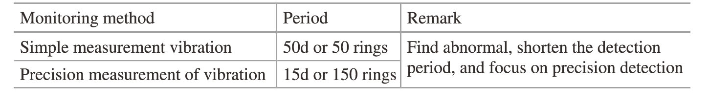
Table 6.9 Vibration monitoring scheme
(1)The surface of the measuring point should be as smooth as possible and the sensor should be installed securely.
(2)The measuring point should be as close as possible to the measured vibration source,so that the vibration signal has the least attenuation during the propagation process.
(3)Prefer the position near the bearing housing.
(4)More points should be arranged near the faulty multiple components.
(5)Low frequency(below 1000 Hz)takes into account three directions of horizontal,vertical and axial directions;high frequency(1000 Hz or higher)can be used in one direction because the direction sensitivity of high frequency vibration signals is poor.
The measuring points of each bearing are the horizontal radial,vertical radial and axial positions of the bearing.The bearings inside the equipment,such as motor bearings and gearbox bearings,are not monitored separately,and the inspection of the corresponding equipment is the main.(https://www.daowen.com)
3)Testing plan
It can be seen from Table 6.8 that the number of detected objects of shield is large and the position is dispersed.In order to reduce the cost of detection system and the workload of detection,the system adopts portable mobile measurement and cooperates with a simple vibration measuring instrument for inspection.The specific detection scheme is shown in Table 6.9.The data of vibration detection need to be systematically managed,especially the simple vibration measuring instrument,which needs to record the data manually and enter into the computer for preservation.In practical application,it is necessary to use infrared thermometer,oil analyzer,mechanical fault hearing device and other simple equipment to grasp the health status of the equipment through various means.
6.2.2.3 System Hardware Configuration
The hardware part of the shield vibration detection system includes vibration acceleration sensor,signal conditioning module,signal acquisition card and notebook computer.
The sensor is used to convert real physical signals into electrical signals.Because the electrical signals output by the sensor are usually weak and accompanied by a large number of noise signals,it is necessary to use signal conditioning devices to regulate them.The functions of signal conditioning devices generally include amplification,isolation,multiplexing,filtering,excitation and linearization.The acquisition card sends the modulated signal to the computer,and then the computer processes,analyzes and displays it.
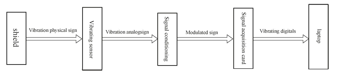
Fig.6.31 The hardware structure of shield vibration detection system composition
Table 6.10 Vibration frequency and amplitude range of each equipment of shield
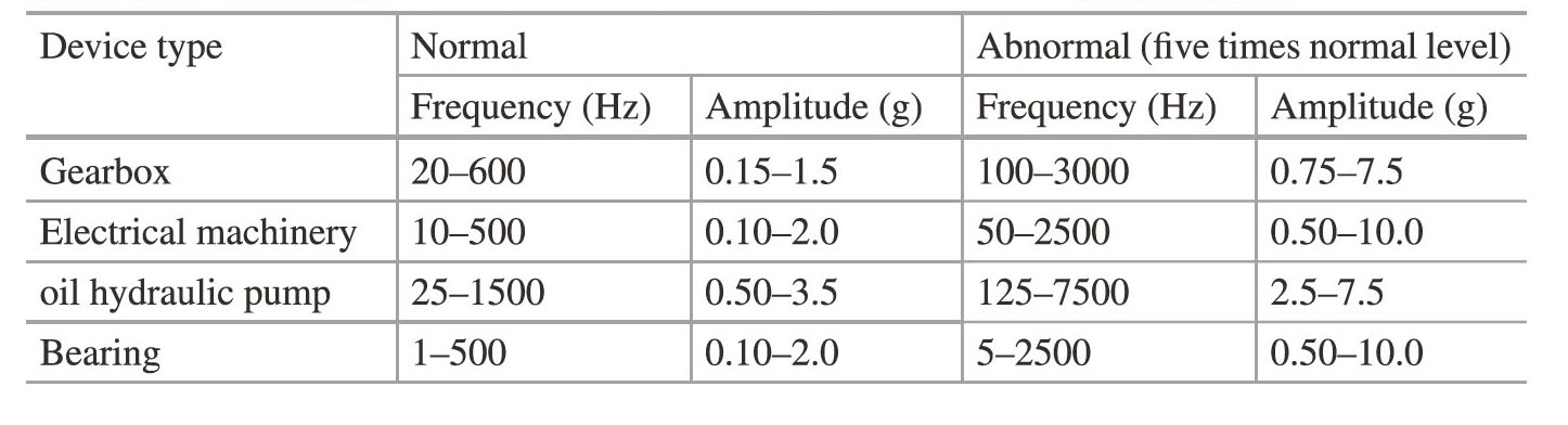
Fig.6.31 shows the hardware structure of the shield vibration detection system.The frequency of each equipment is calculated according to the data detected by the simple vibration tester.The statistics of the vibration frequency and amplitude range of the key equipment of the shield are shown in Table 6.10.Considering the surrounding environment and system cost of the detection object,the magnetic seat installation method is adopted.
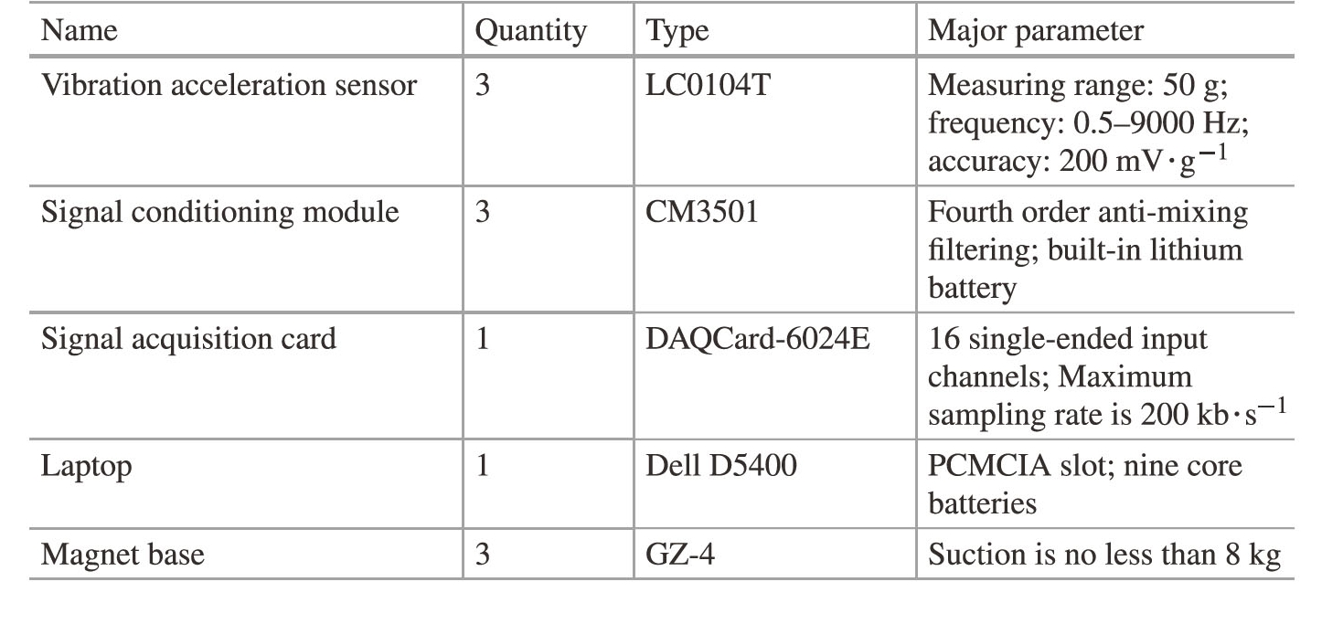
The hardware of the shield vibration detection system is shown in Table 6.11.The overall hardware of the system is compact and portable,and it can be operated by one person without external power supply.The battery runs for more than 4 h,which is sufficient to complete a complete detection.At the same time,the hardware has shielding function,and has certain waterproof,dustproof and seismic ability,which is suitable for complex environment.
6.2.2.4 Software System Development
LabVIEW is a powerful and flexible instrument and analysis software application excavation tool,which is an important part of virtual instrument technology.In the software part of the system,LabVIEW is used as the software platform and combined with the design and development of Access database.The functions of data acquisition,waveform storage,signal processing,data analysis and report generation are completed.Using the characteristics of LabVIEW itself,the modular design and development of software are realized,and the efficiency of program development is greatly improved.The functions of the software part of the system are shown in Fig.6.32.
Table 6.11 Shield vibration detection hardware system
6.2.2.5 Engineering Application
The system has been applied in Nanjing Yangtze River Tunnel since February 2009 to guide the full-line operation of the two tunnels on August 22,2009.During the monitoring process,too many misjudgments were eliminated,and the expensive shutdown was avoided.The detected objects were in good condition and no obvious abnormalities were found.For example,on March 17,2009,a high temperature of P1.1B shaft sleeve bearing occurred,which exceeded the daily temperature by about 20℃.Foreign experts in field work preliminarily judged that the motor was eccentric or different from the load.The system is used to detect the motor.Table 6.12 is the radial vibration time domain statistics of the bearing position at the output end of the motor.By comparing with the vibration value of the motor under normal state,it is found that the amplitude of the statistics increases little,some also appear negative growth,and there is no abnormal increase in statistics.
The spectrum diagram is further observed,as shown in Fig.6.33.If the motor has eccentricity or different load centers,the double frequency of the motor will increase with sideband,and the double grid frequency will also increase significantly with sideband.When the speed of the motor is 398 r/min,the rotating frequency is 6.63 Hz,compared with the spectrum of the motor under normal condition,it can be found that the frequency change of twice the grid is not obvious,and the amplitude change of twice the rotating frequency is not large.Later investigation is due to too much lubricating oil injected into the shaft sleeve,resulting in high temperature bearing.
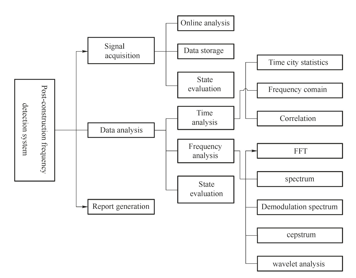
Fig.6.32 Vibration detection software function of shield