Station 1
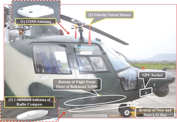
Station 1:Exterior of Cockpit(Right Side of Nose)
(1)GNSS Antenna(43S):It receives satellite positioning signals and sends the signals to GNSS receiver inside the inertial measuring unit.
Key Points to Check:appearance and installation.
(2)Velocity Vector Sensor GSS-1A(102F):It senses total pressure,static pressure,total temperature of the induced airflow and the relative azimuth angle to helicopter coordinates.The data above will further be sent to ADC(air data computer).
Key Points to Check:appearance,installation and flexibility.
(3)Combined Antenna of Radio Compass ZT-9(81R):It receives signals from beacons,radio stations or navigation beacons and sends the signals to the receiver of radio compass WL-9-1.
Key Points to Check:appearance and installation.
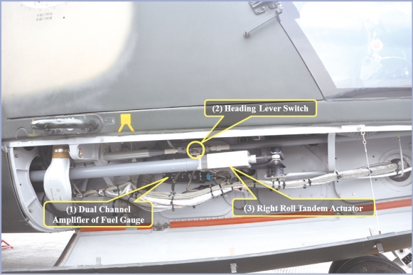
Bottom of Right Front Floor of Bulkhead X2000
(1)Dual Channel Amplifier of Fuel Gauge FUC-46(2Q):It’s a component of BUC-46 capacitive fuel gauge.It processes the change in the capacitance of the fuel gauge sensor and outputs DC voltage in direct proportion to the fuel quantity to the indicator.
Key Points to Check:appearance,installation,cable plug(s)and cable(s).
(2)Heading Lever Switch CHG-1(28C):As a rigid linkage,it transmits the force applied on the pedals to tail rotor through an actuator so that the pilot could change the heading.As an electric switch,when the CSAS(control stability augmentation system)is engaged,it could activate the corresponding electric conversion(cancel anchoring)in the CSAS and affect flight control status based on whether the corresponding switch of the heading channel is connected or not and how much force it senses.
Key Points to Check:appearance,installation,cable plug(s)and cable(s).
(3)Right Roll Tandem Actuator DCD-10(24C):It receives signals from the amplifier,executes control on retraction and extension and feeds back signals to indicate the position of the actuator.
Key Points to Check:appearance,installation,cable plug(s)and cable(s).
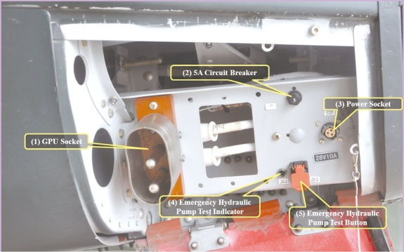
GPU Socket
(1)GPU Socket(23P):It is connected to a ground DC power source and supplies power to heliborne DC power system.
Key Points to Check:appearance,installation and cable(s).
(2)5A Circuit Breaker(11P):It is connected to the ground power over-voltage protection plug-in unit.When the over-voltage protection circuit is shortcircuited,the breaker will be disconnected and ground power will be cut off from heliborne power network.
Key Points to Check:appearance and installation.
(3)Power Socket(90P):It is a standby DC power socket.
Key Points to Check:appearance and installation.
(4)Emergency Hydraulic Pump Test Indicator(24G):If the emergency hydraulic pump works normally in a ground test,the indicator will light up.
Key Points to Check:appearance and installation.
(5)Emergency Hydraulic Pump Test Button(20G):It is used to test the emergency hydraulic pump in a ground test.
Key Points to Check:appearance,installation and flexibility.
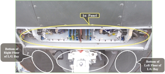
Bottom of Nose
1α Panel:As the main power distribution box,it is equipped with 4 contactors,2 short-circuit protection plug-in units,2 reverse current protectors,2 diode plug-in units,2 reverse current breakers,2 shedding contactors(one for left system and the other for right system),2 ground power relays,2 shortcircuit detection relays and 1 ground power over-voltage protection plug-in unit.
Key Points to Check:appearance and installation.
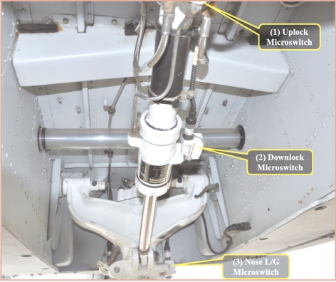
Nose Landing Gear Bay
(1)Uplock Microswitch(6G):It is locked and disconnects the retraction circuit when the landing gear is fully retracted.It is unlocked when the landing gear is being retracted,extended and fully extended,setting the retraction circuit ready.
Key Points to Check:appearance,installation,cable plug(s)and cable(s).
(2)Downlock Microswitch(7G):It is locked and disconnects the extension circuit when the landing gear is fully extended.It is unlocked when the landing gear is being extended,retracted and fully retracted,setting the extension circuit ready.
Key Points to Check:appearance,installation,cable plug(s)and cable(s).
(3)Nose L/G Microswitch(5G):As the microswitch of the shock-absorbing leg,it is engaged when the shock-absorbing leg is compressed and set in neutral position at the same time(when the helicopter is parked on the ground)to prevent the landing gear from being retracted.
Key Points to Check:appearance,installation,cable plug(s)and cable(s).
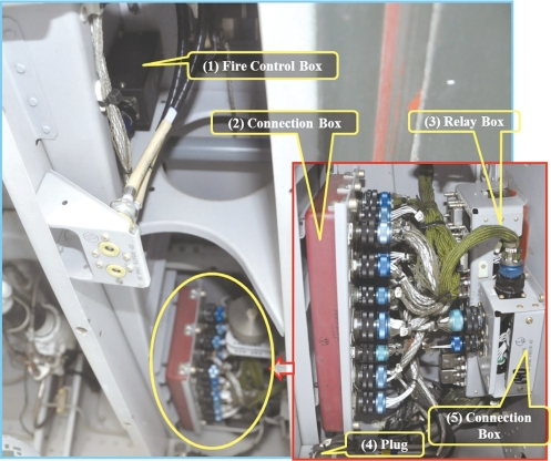
Bottom of Left Floor of Nose Landing Gear Bay
(1)Fire Control Box HKH-8A(7E):When the area temperature of left engine exceeds the warning value,the relay is connected and sends warning signals.When the fire detection circuit is disconnected or grounded,the control box sends failure signals.
Key Points to Check:appearance,installation,cable plug(s)and cable(s).
(2)Connection Box(30α):It consists of the wiring of systems including the hydraulic system,communication system,anti-icing and rain-draining system,landing gear,illumination system,power distribution system and engine control system.
Key Points to Check:appearance,installation,cable plug(s)and cable(s).
(3)Relay Box(23α):It consists of the relays of systems includin the fire extinguisher system,cabin door warning system,hydraulic system and extension/retraction system of the landing gear.
Key Points to Check:appearance,installation,cable plug(s)and cable(s).
(4)Plug(48A):They are the control potentiometers of left and right collective pitch levers and the adapter plug for emergency jettison circuit.
Key Points to Check:appearance,installation,cable plug(s)and cable(s).
(5)Connection Box(31α):It is the connection box of the illumination system and power distribution devices.
Key Points to Check:appearance,installation,cable plug(s)and cable(s).
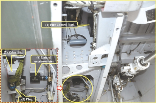
Bottom of Right Floor of Nose Landing Gear Bay
(1)Fire Control Box HKH-8A(7E):When the area temperature of right engine exceeds the warning value,the relay is connected and sends warning signals.When the fire detection circuit is disconnected or grounded,the control box sends failure signals.
Key Points to Check:appearance,installation,cable plug(s)and cable(s).
(2)Relay Box(24α):It consists of the control relays of systems including the fire extinguisher system,hydraulic system,anti-icing and rain-draining system and illumination system.
Key Points to Check:appearance,installation,cable plug(s)and cable(s).
(3)Plug(14α):It is the cable plug of the cyclic pitch lever of the pilot.
Key Points to Check:appearance,installation,cable plug(s)and cable(s).
(4)Lateral Accelerometer GJ-10B(58F):It is used to sense lateral acceleration of the helicopter.It will convert the change in the acceleration into 400Hz signals and input them to the heading channel of the CSAS to realize the coordinated turn of the helicopter.
Key Points to Check:appearance,installation,cable plug(s)and cable(s).
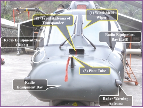
Front of Nose
(1)Windshield Wiper:It is used to wipe off the rainwater and snowflakes on the windshield.Its high speed is not less than 60 times/min,with low speed not less than 40 times/min.The maximum mechanical angle is 45°.Its DC power is 27V and the motor power is 141W.It is not allowed to use windshield wipers on dry windshields.
Key Points to Check:appearance,installation,wiper blades and pressure.
(2)Front Antenna of Transponder(72S):It receives the identification/interrogation signals(in general mode,mode 1,mode 2,mode 3 or mode 4)and non-identification/interrogation signals(batch number and altitude)from ground,shipboard or other airborne interrogators(or interrogator transponders)and then sends such signals to the transponder.
Key Points to Check:appearance and installation.
(3)Pitot Tube:It senses and transmits the value of total pressure to the air speed indicator and ADC.
Key Points to Check:appearance,installation and pipe.
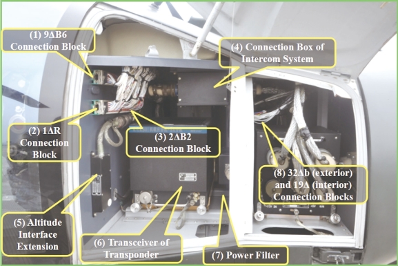
Right Side of Radio Equipment Bay
(1)(2)(3)(8)Connection Block:9ΔB6:connection block of the navigation system and the CSAS;1ΔR:line bank of the intercom system;2BΔ2:connection block of the power system and engine control system;32Δb:connection box of the CSAS,fuel system,hydraulic system and indication system;19Δ:connection box of the anti-icing and rain-draining systems.
Key Points to Check:appearance,installation and cable(s).
(4)Connection Box of Intercom System(22R):It is composed of receiving,transmitting,amplifying,power filtering and warning circuits.Sockets J1,J2 and J3 are connected to the control box.J6 is connected to heliborne radio equipment and the power system.J4 and J5 are not in use.
Key Points to Check:appearance,installation,cable plug(s)and cable(s).
(5)Altitude Interface Extension 9A1(79S):It receives non-calibrated barometric altitude signals from the altimeter and the HADS(Helicopter Air Data System).There are ARINC-429 interface of the HADS and RS-422 altitude interface.
Key Points to Check:appearance,installation,cable plug(s)and cable(s).
(6)Transceiver of Transponder K/LKB015A(70S):It receives and decodes the identification/interrogation signals(in general mode,mode 1,mode 2,mode 3 or mode 4)and non-identification/interrogation signals(batch number and altitude)from ground,shipboard or other airborne interrogators(or interrogator transponders).Then it sends responsive identification/non-identification signals(batch number and altitude)or special responsive signals(in special modes 1 to 5)so that the interrogator could identify the target and record its batch number and altitude.
Key Points to Check:appearance,installation,cable plug(s)and cable(s).
(7)Power Filter 25D(75S):It filters power signals.
Key Points to Check:appearance,installation,cable plug(s)and cable(s).
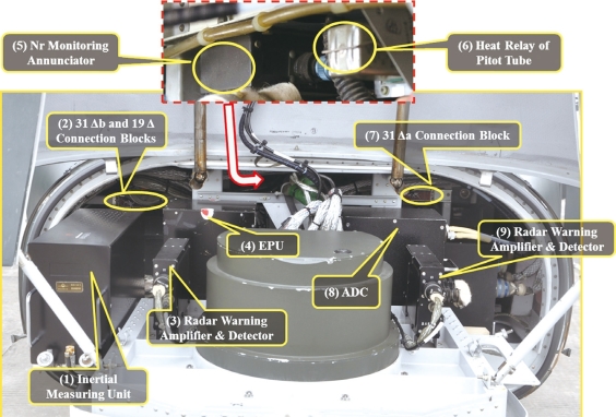
Radio Equipment Bay
(1)Inertial Measuring Unit HJG-1A(41S):It receives and processes acceleration signals and gyroscope signals,and transmits the processed signals to the IDCS(Integrated Display and Control System),IFCS(Integrated Fire Control System)and navigation system.
Key Points to Check:appearance,installation,cable plug(s)and cable(s).
(2)31Δb and 19Δ Connection Blocks:They are the connection blocks of the anti-icing and rain-draining system.
Key Points to Check:appearance,installation and cable(s).
(3)(9)Radar Warning Amplifiers & Detectors ARW9503-1(5T and 8T):They receive radar signals from radar warning antennas and transmit amplified and detected signals to the signal analyzer.
Key Points to Check:appearance,installation,cable plug(s)and cable(s).
(4)EPU EFC-2-02(204E):Engine parameter acquisition unit,or EPU in short,provides DC power at ±15V to the sensors(of the MGB,hydraulic system and engines)in need,acquires necessary data(about the MGB,hydraulic system as well as pressure,temperature,rotation speed,torque and status of engines),and receives parameters including wheel load,power,atmospheric temperature and flight altitude from related sensors and devices.Then it transmits the calculated and processed data to related devices(the EPD and warning indicators).
Key Points to Check:appearance,installation,cable plug(s)and cable(s).
(5)Nr Monitoring Annunciator XJZ-6(11E):Working together with 832E,it monitors Nr and generates high-pitch and low-pitch warning sounds.
Key Points to Check:appearance,installation,cable plug(s),cable(s).
(6)Heat Relay of Pitot Tube(4F):It connects and disconnects the heat circuit of the pitot tube.
Key Points to Check:appearance,installation and cable(s).
(7)31Δa Connection Block:It is a connection block.
Key Points to Check:appearance,installation and cable(s).
(8)ADC XSC-5A(101F):Equipped for the integrated task system,it receives such data as total pressure,static pressure and total temperature of the induced airflow as well as the relative azimuth to helicopter coordinates.Also,it receives data including the vertical overload,rotational angular velocity and helicopter weight from the bus.After processing and calculating these data,it produces parameters needed by the helicopter,such as 3-axis air speed,pressure altitude,vertical speed,total temperature,rotor induced airspeed,sideslip angle and angle of attack.The system is capable of built-in-test(BIT).
Key Points to Check:appearance,installation,cable plug(s)and cable(s).
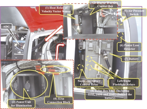
Left Side of Radio Equipment Bay
(1)Heat Relay of Velocity Vector Sensor JKA-52B(106F):It connects and disconnects the heat circuit of the velocity vector sensor.
Key Points to Check:appearance,installation and cable.
(2)Master Warning Control Box KZH-55A(11α):It engages the corresponding warning indicators based on the signals from sensors and provides power to flash the main alarm.
Key Points to Check:appearance,installation,cable plug(s)and cable(s).
(3)Power Unit for Illumination(50L):It provides power to illuminating devices in the cockpit.
Key Points to Check:appearance,installation,cable plug(s)and cable(s).
(4)32Δa Connection Block:It is an adapter module for the CSAS,fire extinguisher system,fuel system,hydraulic system,indication system and landing gear system.
Key Points to Check:appearance,installation and cable(s).
(5)Air Pressure Switch(4G):It is connected to the landing gear warning indicator on the instrument panel.If the landing gear is not fully extended and locked when air speed is lower than 101.92km/h(55kn),it will send warning signals.
Key Points to Check:appearance,installation,cable plug(s)and cable(s).
(6)Power Loss Detector XJZ-2A(32E):It receives signals from the Nf sensor.When Nf is up to the warning limit,the detector is grounded and the corresponding power loss indicator lights up(Warning limit:313r/min.Precision:±1%).Warning signals will be transmitted(the indicator is on)when Nf is up to the warning limit until the engine shuts down.
Key Points to Check:appearance,installation and cable(s).
(7)Battery(22P):It is the emergency and backup DC power source at a rated capacity of 36Ah and rated voltage of 24V.
Key Points to Check:appearance,installation,cable plug(s)and cable(s).
(8)Relay Box(130E,including 115E,103E and 104E):If one engine fails and the torque difference between two engines ΔC exceeds 25%,it connects the circuit to light up the super-emergency power indicator(on top of the EPD).
Key Points to Check:appearance,installation,cable plug(s)and cable(s).
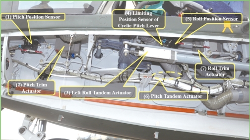
Bottom of Left Front Floor of Bulkhead X2000
(1)Pitch Position Sensor GE-23(71C):It senses and transmits the signals that indicate longitudinal angle position to the computer.
Key Points to Check:appearance,installation,cable plug(s)and cable(s).
(2)Pitch Trim Actuator DCD-9(21C):It receives computer instructions and establishes an anchoring point for the control linkage.There is a damper.The actuator will be anchored when the electromagnetic clutch is not engaged(not switched on).A load sensitive switch will release the lever force when certain force is applied on the cyclic pitch lever.
Key Points to Check:appearance,installation,cable plug(s)and cable(s).
(3)Left Roll Tandem Actuator DCD-10B(25C):It receives signals from the amplifier,executes control on retraction and extension and feeds back signals to indicate the position of the actuator.
Key Points to Check:appearance,installation,cable plug(s)and cable(s).
(4)Limiting Position Sensor of Cyclic Pitch lever:It sends signals to the corresponding indicator“Limit”when the cyclic pitch lever is on left or right limiting position.
Key Points to Check:appearance,installation,cable plug(s)and cable(s).
(5)Roll Position Sensor GE-23(73C):It senses and transmits the signals that indicate horizontal angle position to the computer.
Key Points to Check:appearance,installation,cable plug(s)and cable(s).
(6)Pitch Tandem Actuator DCD-10(23C):It receives signals from the amplifier,executes control on retraction and extension and feeds back signals to indicate the position of the actuator.
Key Points to Check:appearance,installation and cable(s).
(7)Roll Trim Actuator DCD-9(27C):It receives computer instructions and establishes an anchoring point for the control linkage.There is a damper.The actuator will be anchored when the electromagnetic clutch is not engaged(not switched on).A load sensitive switch will release the lever force when certain force is applied on the cyclic pitch lever.
Key Points to Check:appearance,installation,cable plug(s)and cable(s).
