Station 2

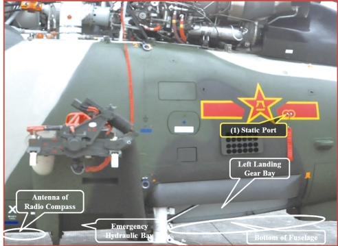
Station 2:Left Side of Fuselage
(1)Static Port:It senses and transmits static pressure to the total-static system and air data calculator.
Key Points to Check:appearance and blockage.

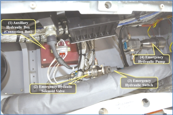
Emergency Hydraulic Bay
(1)Auxiliary Hydraulic Box(Connection Box)(19G):It is the connection box of the auxiliary hydraulic system.
Key Points to Check:appearance,installation,cable plug(s)and cable(s).
(2)Emergency Hydraulic Solenoid Valve YDK-12(26G):When powered on,it opens the pipes of the emergency hydraulic system.
Key Points to Check:appearance,installation,cable plug(s),cable(s)and leakage.
(3)Emergency Hydraulic Switch YCG-3(23G):It lights up an indicator when the emergency hydraulic pressure exceeds 95 bars to indicate that the emergency system is working.
Key Points to Check:appearance,installation,cable plug(s),cable(s)and leakage.
(4)Emergency Hydraulic Pump YCB-0.25(21G):It supplies hydraulic oil to main and auxiliary hydraulic systems when the main hydraulic system fails.
Key Points to Check:appearance,installation,cable plug(s),cable(s)and leakage.

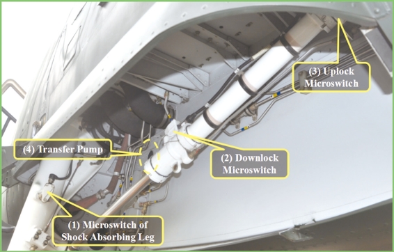
Left Landing Gear Bay
(1)Microswitch of Shock-absorbing Leg(9G):It senses if the landing gear has left the ground so as to prevent it from being retracted when the shockabsorbing leg is not fully extended(or not off the ground).
Key Points to Check:appearance,installation,cable plug(s)and cable(s).
(2)Downlock Microswitch(13G):It disconnects the circuit of the hydraulic solenoid valve and sets the retraction circuit ready when the landing gear is fully extended.
Key Points to Check:appearance,installation,cable plug(s)and cable(s).
(3)Uplock Microswitch(11G):It disconnects the circuit of the hydraulic solenoid valve and sets the extension circuit ready when the landing gear is fully retracted.
Key Points to Check:appearance,installation,cable plug(s)and cable(s).
(4)Transfer Pump RXB-4(20Q):It transfers fuel from one tank group to the other.
Key Points to Check:appearance,installation,cable plug(s),cable(s)and leakage.

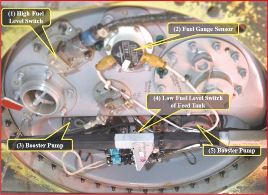
Bottom of Fuselage(Left)
(Right side is the same but without the high fuel level switch)
(1)High Fuel Level Switch XU-24(9Q):During fuel transfer,it will be connected and light up indicator“HI.LEV”when the fuel tank receiving fuel is full.
Key Points to Check:appearance,installation,cable plug(s),cable(s)and leakage.
(2)Fuel Gauge Sensor GUC-46/3(5Q):It is a component of the capacitive fuel quantity measuring unit,providing data of the quantity of the fuel stored in the fuel tank.
Key Points to Check:appearance,installation,cable plug(s),cable(s)and leakage.
(3)(5)Booster Pumps RLB-12(7Q and 69Q):They raise pressure in fuel pipes.
Key Points to Check:appearance,installation,cable plug(s),cable(s)and leakage.
(4)Low Fuel Level Switch of Feed Tank XU-24/3(11Q):It is connected and lights up indicator“FUEL.Q”on 3Q panel when there is less than 18L of fuel in the feed tank.Indicator“FUEL.Q”on 7α panel also lights up.It also connects the logic circuit 11α of the warning system and lights up indicator“ALARM”on the instrument panel.
Key Points to Check:appearance,installation,cable plug(s),cable(s)and leakage.
