Adjustment and Balance Check on Generator Voltage ...
1.Equipment Needed
One C31-VA DC voltmeter at an accuracy of 1.5
Note:This procedure is conducted when it is the first ground operation adjustment or when a voltage regulator is newly installed.
2.Preparations
·Set the helicopter ready and make sure the battery is installed properly and fully charged.
·Open the cargo bay door.
·Open left and right electric equipment panels.
·Put switches“BAT.RLY1”,“BAT.RLY2”,“GEN1”and“GEN2”at“ON”position.
·Start engines and wait until their rotation speed reaches the rated value.Generators can only be connected with the power network after they enter the rated state(indicators“GEN1”and“GEN2”go out).
Note:When atmospheric temperature reaches or exceeds 35℃,it is advised to set the voltage of the helicopter to 27.5±0.5V.Otherwise,the voltage shall be set at 28.5±0.5V.
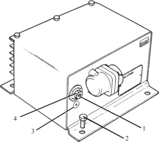
3.Testing Procedures(see the figure below)
(1)Voltage Check and Adjustment for No-load Generators.
·Put switches“GEN.1”and“GEN.2”at“OFF”position.Indicators“GEN.1”and“GEN.2”light up.
·Connect the voltmeter with left generator,then with right one:the positive wire is connected to the binding post(3)of the test socket of the corresponding voltage regulator while the negative wire is connected to the fuselage(fastening screw of the voltage regulator(2)).
·Record the voltage of each generator.
·If necessary,adjust the voltage to 28.5V,loosen the locking nut(4)and rotate the adjusting screw(1)to adjust the voltage(28.5±0.5V or 27.5±0.5V as required).Then fasten the locking nut and the voltage shall not change.If not,adjust again.
·Disconnect the voltmeter.
·Put switches“GEN.1”and“GEN.2”at“ON”position.Indicators“GEN.1”and“GEN.2”go out.
·Close left and right electric equipment panels.
·Close cargo bay door.
(2)Balance Check and Adjustment.
Put selector 10α on 6α panel at“GEN.1”position.
·Put switch“BAT.RLY1”at“OFF”position and indicator“BAT.SW1”lights up.
·Switch off Generator 1 and indicator“GEN.1”lights up.
·Check if the voltage of Generator 1 is the same as the adjusted voltage.
·Switch on Generator 1 and indicator“GEN.1”goes out.
·Switch off Generator 2 and indicator“GEN.2”lights up.
·Check the output current value of Generator 1.
·Switch on Generator 2 and indicator“GEN.2”goes out.
·Put switches“BAT.RLY1”and“BAT.RLY2”at“ON”position simultaneously.And indicators“BAT.SW1”and“BAT.SW2”go out.
Put selector 10α at“GEN.2”position.
·Put switch“BAT.RLY2”at“OFF”position and indicator“BAT.SW2”lights up.
·Switch off Generator 2 and indicator“GEN.2”lights up.
·Check if the voltage of Generator 2 displayed on the EPD is the same as the adjusted voltage.
·Switch on Generator 2 and indicator“GEN.2”goes out.
·Switch off Generator 1 and indicator“GEN.1”lights up.
·Check the output voltage of Generator 2.The value shall be the same as that of Generator 1.
·Switch on Generator 1 and indicator“GEN.1”goes out.
·Put switches“BAT.RLY1”and“BAT.RLY2”at“ON”positions simultaneously.And indicators“BAT.SW1”and“BAT.SW2”go out.
·Check the output voltage and current of Generator 2 and set selector 10α at“GEN.1”position.
·Check the output voltage and current of Generator 1.
·Normally,the voltage of Generator 1 shall be the same as that of Generator 2.The output current of each generator is about 40A(25%)and the output current difference shall not exceed 10A.Otherwise,re-adjust the voltage.
·Reduce the voltage of the generator under greater load to reduce its load.


Voltage Regulator
