Station 11
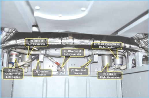
Station 11:Cargo Bay(Front)
(1)(7)Start Contactors of Left and Right Engines(25P and 24P):They connect the start circuits of starter generators during engine start.
Key Points to Check:appearance,installation,cable plug(s)and cable(s).
(2)(6)Filters of Left and Right Generators(27P and 26P):They filter AC interference during power generation and restrain radio jamming through wave filtering during engine start.
Key Points to Check:appearance,installation,cable plug(s)and cable(s).
(3)(5)Overheat Sensors(33W and 32W):The bimetallic strips of overheat detectors are disconnected when the temperature in the cargo bay reaches 110℃ and indicator“O/HEAT”on 7α panel lights up.
Key Points to Check:appearance,installation,cable plug(s)and cable(s).
(4)Diverter of Left Generator(33P):It measures the value of output current of the generator.The rated current value is 160A.
Key Points to Check:appearance,installation,cable plug(s)and cable(s).
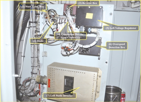
Left Electric Equipment Panel 21α
(1)Start Relay Box(7K):It is the relay box for engine start control.
Key Points to Check:appearance,installation,cable plug(s)and cable(s).
(2)Resistor Box:It is the resistor box(including 17W,19W,29W and 31W)for circuit compensation of the fire extinguisher system.
Key Points to Check:appearance,installation and cable(s).
(3)Diode(117P):It is the diode of the left voltage regulator.
Key Points to Check:appearance,installation and cable(s).
(4)Connection Box for Start Control 1Δ:It is the connection block of control circuits of the left engine and left power system.
Key Points to Check:appearance,installation and cable(s).
(5)Left Voltage Regulator TKB-3(29P):It monitors the working status of the generator and regulates its output voltage.It has three functions:regulation(regulation of voltage during power generation and regulation of currents during engine start),control and protection.
Key Points to Check:appearance,installation,cable plug(s)and cable(s).
(6)Overspeed Detection Box(6K):It works together with the overspeed sensor to detect an overspeed.Normally,indicator“O/SPEED”lights up when Ng is below 25%.When an overspeed occurs(Ng>123.1%),it activates the overspeed cut-off solenoid valve to shut down the engine.There are also a test button and a reset button on the box.
Key Points to Check:appearance,installation,cable plug(s)and cable(s).
(7)Left Static Inverter PC-1000(41X):It converts DC power into AC power for AC power consuming devices on board.It converts direct currents at 28V into two sets of alternate currents:115V/400Hz and 26V/400Hz.
Key Points to Check:appearance,installation,cable plug(s)and cable(s).
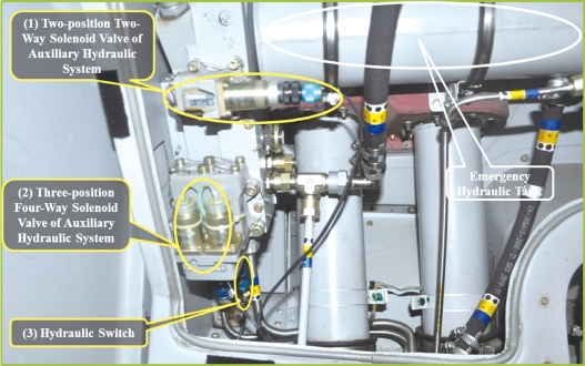
Auxiliary Hydraulic Regulator
(1)Two-position Two-way Solenoid Valve of Auxiliary Hydraulic System YDK-11(15G):It is the control valve of the auxiliary hydraulic system.When it is switched on,the hydraulic oil in the pipes flows back to the tank.When it is switched off,the hydraulic oil could be pressurized.
Key Points to Check:appearance,installation,cable plug(s)and cable(s).
(2)Three-position Four-way Solenoid Valve of Auxiliary Hydraulic System YDK-10(16G):It controls the retraction and extension of the landing gear by controlling the flowing direction of the hydraulic oil.
Key Points to Check:appearance,installation,cable plug(s)and cable(s).
(3)Hydraulic Switch YCG-4(22G):It lights up indicator“AUX.HYD”when the auxiliary hydraulic pressure exceeds 2.5±0.5MPa.
Key Points to Check:appearance,installation,cable plug(s)and cable(s).
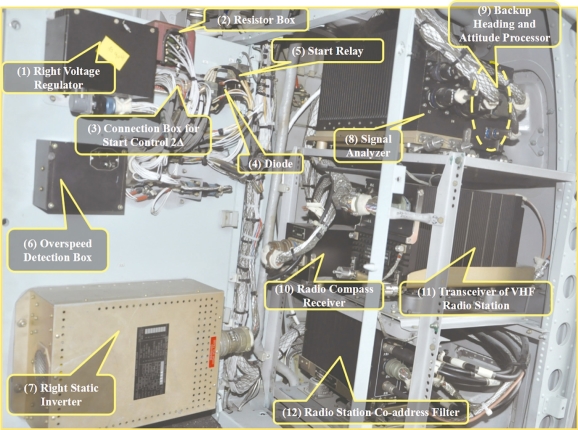
Right Electric Equipment Panel 22α
(1)Right Voltage Regulator TKB-3(28P):It monitors the working status of the generator and regulates its output voltage.It has three functions:regulation(regulation of voltage during power generation and regulation of currents during engine start-up),control and protection.
Key Points to Check:appearance,installation,cable plug(s)and cable(s).
(2)Resistor Box:It is the resistor box(including 18W,20W,28W and 30W)for circuit compensation of the fire extinguisher system.
Key Points to Check:appearance,installation and cable(s).
(3)Connection Box for Start Control 2Δ:It is the connection block of the control circuits of the right engine and right power system.
Key Points to Check:appearance,installation and cable(s).
(4)Diode(118P):It is the diode of the right voltage regulator.
Key Points to Check:appearance,installation and cable(s).
(5)Start Relay Box(8K):It is the relay box for engine start control.
Key Points to Check:appearance,installation,cable plug(s)and cable(s).
(6)Overspeed Detection Box(5K):It works together with the overspeed sensor to detect an overspeed.Normally,indicator“O/SPEED”lights up when Ng is below 25%.When an overspeed occurs(Ng>123.1%),it activates the overspeed cut-off solenoid valve to shut down the engine.There are also a test button and a reset button on the box.
Key Points to Check:appearance,installation,cable plug(s)and cable(s).
(7)Right Static Inverter PC-1000(40X):It converts DC power into AC power for AC power consuming devices on board.It converts direct currents at 28V into two sets of alternate currents:115V/400Hz and 26V/400Hz.
Key Points to Check:appearance,installation,cable plug(s)and cable(s).
(8)Signal Analyzer(9T):It receives and processes the radar signals from the amplifier and detector,and further transmits the processed signals to IDCS.
Key Points to Check:appearance,installation,cable plug(s)and cable(s).
(9)Backup Heading and Attitude Processor(112F):It receives and processes magnetic heading and radio heading signals.Then it transmits processed signals to the IDCS to provide backup heading to the helicopter.
Key Points to Check:appearance,installation,cable plug(s)and cable(s).
(10)Radio Compass Receiver:It receives and processes signals from the combined antenna.Then it transmits the processed bearing signals to the HSI and audio signals to the intercom system.It could work in RECEIVE mode and Compass mode.
Key Points to Check:appearance,installation,cable plug(s)and cable(s).
(11)Transceiver of VHF Radio Station TKR128(10R):Capable of signal reception and transmission,it is used for plain/secure communications between helicopters and between helicopters and the ground.
Key Points to Check:appearance,installation,cable plug(s)and cable(s).
(12)Radio Station Co-address Filter:It reduces the noises in spare bands during signal transmission of a radio station and restrains transmission/reception interference to multiple co-address devices,so as to improve the ability of co-address communications for multiple communication devices.
Key Points to Check:appearance,installation,cable plug(s)and cable(s).
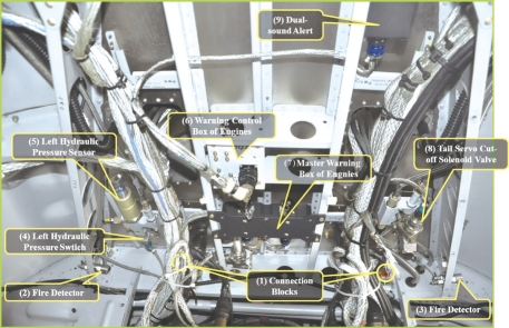
Ceiling of Cargo Bay(Forward)
(1)Ground Blocks(15N and 16N):They are the connection points of ground leads.
Key Points to Check:appearance,installation and cable(s).
(2)(3)Fire Detectors(25W and 26W):They detect fire in the cargo bay.Indicator“CARGO.F”lights up when the temperature reaches 160℃.
Key Points to Check:appearance,installation and cable(s).
(4)Left Hydraulic Pressure Switch YCG-4(5D):It measures the hydraulic pressure and activates the circuit when the pressure reaches the preset max/min warning values.The indicator goes out when the hydraulic pressure rises to 2.5±0.5MPa and lights up when the hydraulic pressure drops below 1+0.5MPa.
Key Points to Check:appearance,installation,cable plug(s),cable(s)and leakage.
(5)Left Hydraulic Pressure Sensor CY-YZ-0101-10(3D):It provides the pressure signals of the main hydraulic system(0-10MPa).
Key Points to Check:appearance,installation,cable plug(s),cable(s)and leakage.
(6)Warning Control Box of Engines(815K):It is the power unit of audio warning and supplies power to the audio warning device of the engine.
Key Points to Check:appearance,installation,cable plug(s)and cable(s).
(7)Master Warning Box of Engines(810K):It receives and processes signals from the EPU and further transmits audio warning signals to headsets.
Key Points to Check:appearance,installation,cable plug(s)and cable(s).
(8)Tail Servo Cut-off Solenoid Valve YDK-12(12D):It cuts off hydraulic oil supply automatically when there is less than 2L of hydraulic oil in the tail rotor hydraulic system(right hydraulic tank).
Key Points to Check:appearance,installation,cable plug(s)and cable(s).
(9)Dual-sound(gong sound)Alert BJQ-1(813K):When Ng of one engine exceeds 100.4% of the maximum take-off power or the torque summation of two engines exceeds 102.5%,it transmits intermittent warning sounds to headsets.When one engine fails and the torque difference between two engines exceeds 25%,it transmits continuous warning sounds to headsets to warn the flight crew.Indicator“LIMIT”in the cockpit also lights up.
Key Points to Check:appearance,installation,cable plug(s)and cable(s).
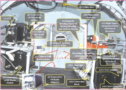
Cargo Bay(Backward)
(1)(3)Cables of VHF Radio Stations:They are connection cables.
Key Points to Check:appearance,installation,cable(s).
(2)Magnetic Heading Sensor of INS HJG-1A(42S):It measures the relative heading of the carrier to geomagnetic North Pole.It works with HJG-1A Inertial Navigation System to provide the relative angle of deflection to geomagnetic North Pole to strap-down inertial navigation system.
Key Points to Check:appearance,installation,cable plug(s)and cable(s).
(4)Receiving/Transmitting Antennas of Radio Altimeter(13S and 14S):They transmit and receive FM signals to measure altitude of the helicopter.
Key Points to Check:appearance,installation,cable plug(s)and cable(s).
(5)Magnetic Heading Sensor of Backup Heading and Attitude System(113F):It measures parameters of magnetic heading and provides backup heading.
Key Points to Check:appearance,installation,cable plug(s)and cable(s).
(6)Transceiver of Radio Altimeter GG0.6-1F(11S):It measures real-time absolute altitude of the helicopter.
Key Points to Check:appearance,installation,cable plug(s)and cable(s).
(7)ATU(11R):It is the antenna tuning unit of the short-wave radio station.It matches the impedance between the transmitter and the antenna,so that the antenna could achieve maximum radiation power at any frequency.
Key Points to Check:appearance,installation,cable plug(s)and cable(s).
(8)Transceiver of VHF Radio Station (50R):As the transceiver of VHF FM,AM and anti-jamming radio stations,it can be used for air-to-air and airto-ground voice communications.
Key Points to Check:appearance,installation,cable plug(s)and cable(s).
(9)Transceiver of HF Radio Station (10R):It receives and processes signals in the short wave band.
Key Points to Check:appearance,installation,cable plug(s)and cable(s).
(10)Flight Data Recorder:It is an anticollision recorder of flight data.
Key Points to Check:appearance,installation,cable plug(s)and cable(s).
(11)(12)Right/Left Super-emergency Power Detector and Recorder of(114E and 113E):When an engine holds super emergency power for more than 5 seconds,the warning flag on the super-emergency detector and recorder will turn from black to red.And the flash relay of this engine will be connected and the super-emergency power warning indicator lights up.There is also a life timer.
Key Points to Check:appearance,installation,cable plug(s)and cable(s).
(13)CSAS Amplifier FKJ-10(19C):It controls pitch and roll double-motor actuators as well as the yaw actuator based on computer instructions.Also,it provides various signals needed by the computer and monitors the circuits.
Key Points to Check:appearance,installation,cable plug(s)and cable(s).
(14)CSAS Computer SJ-2C(16C):It processes signals from the gyro horizon,strapdown inertial navigation system and HADS.It also works with the coupler console and transmits processed signals to execution mechanisms to enable such functions as stability holding and auto-navigation of the helicopter.
Key Points to Check:appearance,installation,cable plug(s)and cable(s).
(15)(16)Connection Blocks(9ΔA1 and 9ΔB1):They are connection blocks.
Key Points to Check:appearance,installation and cable(s).
(17)Filter Box ELB-1(650C):As a component of the CSAS,it is used to filter feedback position signals of the heading control actuator and HF interference of ±15V power.
Key Points to Check:appearance,installation,cable plug(s)and cable(s).
