2.5 Overall Shear Failure of Cantilever Walls
Theoretically speaking,the overall shear failure analysis of a cantilever wall should include analyses of push⁃in failure and basal heave failure.However,the stability of the cantilever wall is rather weak and its application is usually confined to sand,gravelly soils or stiff clays.
On soft clay,the cantilever wall is not reliable enough.Since no basal heave failure is found in sandy gravel soils or stiff clays,as far as the cantilever wall is concerned,only analysis of push⁃in failure is required.
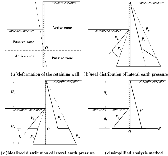
The stability of a cantilever wall counts on the soil reaction at a specific fixed point.The design is therefore confined to the fixed earth support method and the free earth support method is inapplicable.Figure 2.17(a)illustrates a cantilever wall rotating about point O in a limiting state.Figure 2.17(b)shows the earth pressure on the retaining wall.For the simplification of analysis,assume the active and passive earth pressures above and below point O are fully mobilized and therefore the earth pressure distribution is discontinuous around point O as shown in Figure 2.17(c).
See the earth pressure distribution as shown in Figure 2.17(c),and Hp and L are unknown.With the horizontal force equilibrium and the moment equilibrium,we would obtain the required penetration depth.Since both the horizontal force equilibrium and the moment equilibrium will generate quadratic and cubic equations,it is not easy to solve the equations directly.The trial⁃and⁃error method is not less complicated,so it is necessary to simplify the analysis method for practical use.
Figure 2.17(d)illustrates the simplified earth pressure distribution where the concentration force,R represents the difference between the passive earth pressure from outside the excavation zone and the active earth pressure from inside the excavation zone below the turning point O.It is necessary that R exists to keep the horizontal force equilibrium.Based on the moment equilibrium against point O,we can find the value d0.Because of the simplification of the analysis,d0 should be slightly smaller than the actually required penetration depth and has to be increased properly(generally,20%).The increment has to be examined to make R satisfy the horizontal force equilibrium as shown in Figure 2.17(d).The detailed computing process can be found in Example 5.4.The simplified analysis method as shown in Figure 2.17(d)has been commonly adopted in engineering design(Padfield and Mair,1984).

Figure 2.17 Analysis of a cantilever wall by gross pressure method
Excavation in a sandy ground with groundwater on both sides of the retaining wall should be analyzed in terms of the distribution of net water pressure as discussed in Section 2.3,viewed as the driving force,following the method shown in Figure 2.17(d).In clayey soils,even though there exists groundwater,water pressure is not to be considered because the undrained analyses have considered the water pressure automatically.
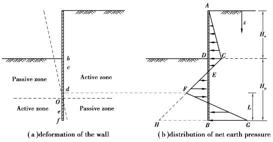
Figure 2.18 shows the net earth pressure distribution.According to the characteristics of the deformation of the cantilever wall,we can see the earth pressures at point b(excavation surface)on the front and back of the retaining wall should achieve the passive earth and the active earth pressures,respectively.The net value of the earth pressure at the point is CD[Figure 2.18(b)].Point c is close to point b and the earth pressures on the front and the back of the wall should also achieve the passive and active earth pressures separately.Thus,the net earth pressure at point c should be
σh,c=[γHe+γ(z-He)]Ka-γ(z-He)Kp=γHeKa-γ(z-He)γ(Kp-Ka)
where
γ=unite weight of the soil;
Ka=coefficient of the active earth pressure;
Kp=coefficient of the active earth pressure.
We can see from the above equation that the slope of line CF is 1∶γ(Kp-Ka)(the vertical∶the horizontal).The net earth pressure with the slope 1∶γ(Kp-Ka)maintains till point d,where the passive and active earth pressures“begin”not to be fully mobilized.Assuming the lateral movement of the bottom of the wall is large enough,the soil in front and back of the wall will reach the active and passive states,respectively,and the net value of the earth pressure here is BG.The soil strength between points f and d in front and in back of the wall may not be fully mobilized TO simplify the analysis,we assume the net earth pressures between points d and f are of a linear relation,as line FG.Figure 2.18(b)shows an assumed net earth pressure distribution.According to the relation of the horizontal force equilibrium in Figure 2.18(b),we know
Area ACE-Area EFHB+Area FHBG=0
We can find L according to the above equation.Substitute L in the moment equilibrium equation with regard to point f′and we have the quadratic equation with Hp as a single unknown variable.To solve Hp,the trial⁃and⁃error method is recommended.When performing trial and error,we usually begin from Hp=0.75He.

Figure 2.18 Analysis of a cantilever wall by net pressure method
