3.4.1 Numerical schemes
Figure 3.14 shows a typical cross⁃section and plan view for the cases considered.The parameters shown in the figure include L=excavation length,B=excavation width,D=wall penetration depth,T=clay thickness below the final excavation level(FEL),SH=horizontal strut spacing,SV=vertical strut spacing and He=depth of final excavation.Vertical retaining walls along the excavation boundary were installed together with a five⁃level strut and waling system.
For 2D analyses,a half mesh was used due to geometrical symmetry.A very fine mesh size was used for 2D analysis to improve the accuracy of FE calculations.For 3D analyses,a medium mesh size in the horizontal direction and medium coarse mesh size in vertical direction were used to reach a balance between processing time and accuracy.
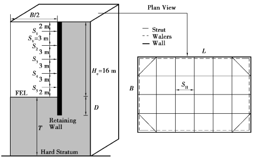
Figure 3.14 Cross⁃section and plan view of the model for braced excavation
For the 2D simulations,fourth⁃order 15⁃node triangular elements,which are considered to be very accurate elements,were used to model the soil while the interface elements have 5 integration points.In 3D PLAXIS,the interface elements have 9⁃point Gauss integration with three translational degrees of freedom for each node.This is described in greater detail in Van Langen(1991).For the 2D analysis,the retaining wall is simulated using 5⁃node elastic plate elements.The elastic behaviour is defined by the following parameters:EA(normal stiffness),EI(bending stiffness,m),and Poisson's ratio.For the 3D analysis,the wall is simulated using 8⁃node quadrilateral plate elements with six degrees of freedom per node.For brevity,only a typical 3D half mesh is shown in Figure 3.15,comprising of 15,679 nodes and 4,980 15⁃noded wedge elements.
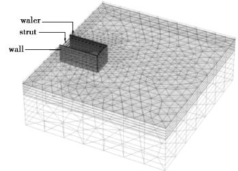
Figure 3.15 3D half mesh of the excavation from PLAXIS 3D foundation
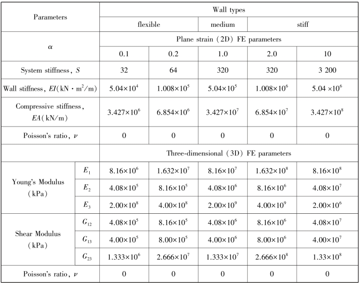
Three wall types,with five different stiffness values,were considered for each soil type as listed in Table 3.3.Based on the approach adopted by Finno et al.(2007),the wall thickness of 0.42 m was set to an arbitrary(constant)value so that the moment of inertia I and area A were kept constant,and only the wall elastic modulus E was varied.A wall stiffness coefficientαwas introduced to represent walls with different rigidities(Bryson and Zapata⁃Medina,2012)as shown in Table 3.3.The baseline bending stiffness EI for the analysis is 5.04×10⁵ kN·m2/m,which refers to a wall of medium stiffness based on the databases of Long(2001)and Moormann(2004).Therefore,α=1.0 is for cases with this medium wall stiffness.For flexible walls,the baseline bending stiffness EI of 5.04×10⁵ kN·m2/m was multiplied by smaller factors of 0.1 and 0.2,while for stiff walls,the baseline bending stiffness was multiplied by larger factors of 2 and 10.The system stiffness,S(Clough et al.,1989)in Table 3.3 is defined as

where
EI=wall stiffness;
γw=unit weight of water;
havg=average vertical strut spacing.
Table 3.3 Wall properties for 2D and 3D analyses
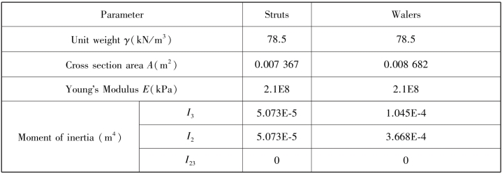
The struts were simulated using node⁃to⁃node anchor elements in 2D analyses.For 3D analyses,the struts and walers were modeled as beam elements,which have six degree of freedom per node,and the struts were placed horizontally at a spacing of 4 or 5 meters(for different case studies)in two directions to form a frame net.The walings were used to connect the excavation wall and the struts.The material properties are tabulated in Table 3.4.
Table 3.4 Properties of waling system
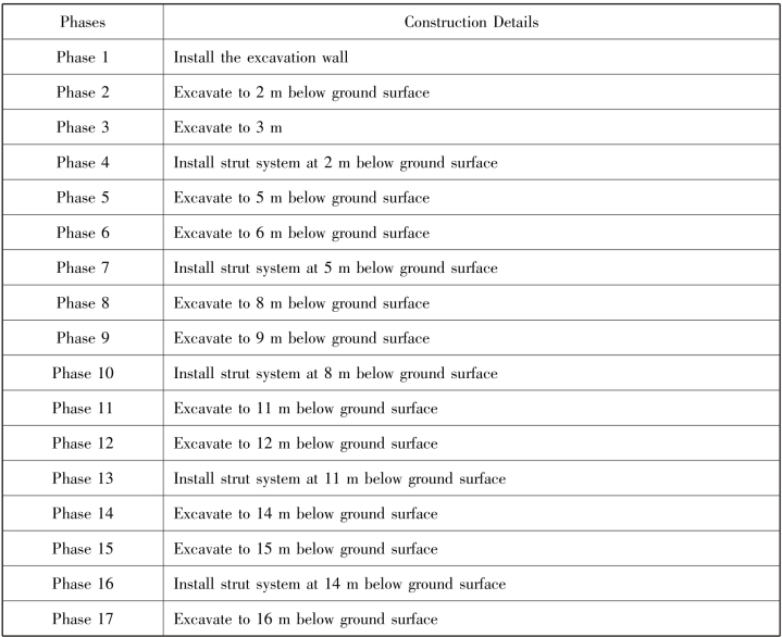
A typical staged construction simulation is shown in Table 3.5.The original ground water table was assumed to be 2 m below the ground surface in the retained soil.The water table inside the excavation was progressively lowered with the excavation of the soil during each phase.
Table 3.5 Typical construction sequence for 2D analyses
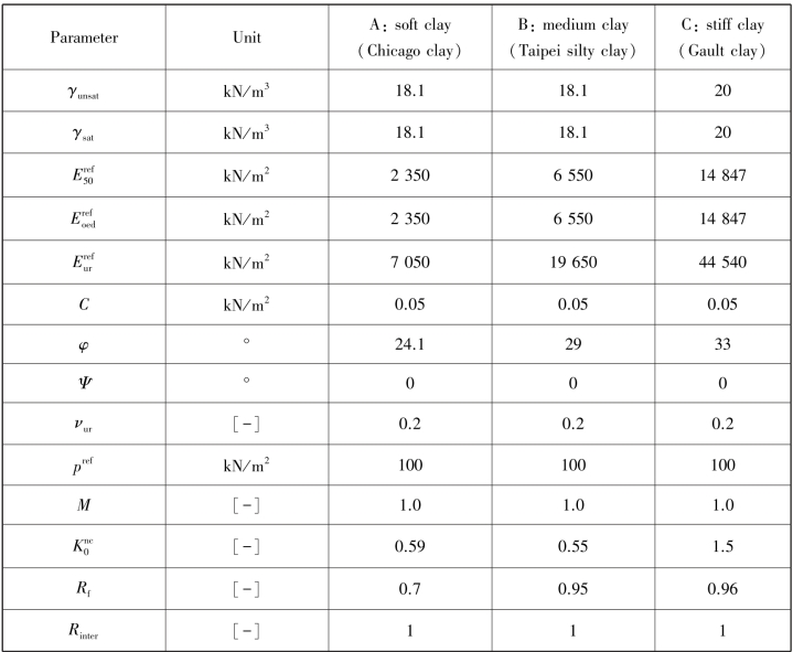
The properties of three different types of clays which were considered in this parametric study are similar to the properties assumed by Bryson and Zapata⁃Medina(2012)and are tabulated in Table 3.6.The soils are assumed to follow the Hardening Soil(HS)model.The three soil types are soft clay,medium clay and stiff clay.The clays are real soils whose properties have been extensively reported in the literature.The properties of the soft clay with average cu=20 kPa are based on the Upper Blodgett soft clay reported by Finno et al.(2002).The medium clay with average cu=45 kPa are based on the Taipei silty clay found at the Taipei National Enterprise Center(TEC)project(Ou et al.,1998).The Gault clay at Cambridge(Ng,1992;Ng and Yan,1998)with average cu=125 kPa was used as the model for the stiff clay.
Table 3.6 Input HS soil parameters of three clays
