4.3.2 Beam on Elastic Foundation Method
The finite element method and the beam on elastic foundation method are two commonly used numerical methods.Theories concerning the finite element method are quite complicated and some of them are not fully developed.The finite element analysis normally requires enormous preprocessor and postprocessor time,computation time,and analysts have to be well equipped with comprehensive geotechnical knowledge and experience.Thus,the method is not widely adopted in the analysis and design of excavations.The beam on elastic foundation method,on the other hand,is simpler in its analysis model.With succinct input parameters,it does not take much time for processing and therefore is favored by most engineers.Nevertheless,the simplicity of the beam on elastic foundation method requires more delicacy and prudence when dealing with complicated excavation problems so that mistakes can be avoided.
In foundation engineering,the soil⁃structure interaction problem is often simulated as a series of springs to simplify analysis.Among them,Winkler's model(Winkler,1867)is most widely applied.
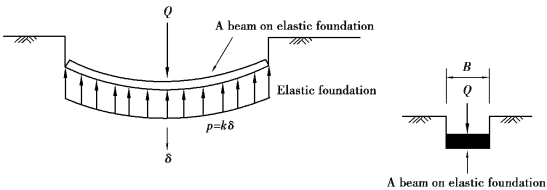
As shown in Figure 4.13,the basic assumption of the Winkler model is given that the foundation is a structure with stiffness and soils are of elastic foundation,their interaction can be simulated as a series of individual springs.The spring constant is the ratio of stress(p)to displacement(δ),which can be expressed as follows:
![]()
where the constant ks is called the coefficient of subgrade reaction,the modulus of subgrade reaction,or the soil spring constant,the unit of which is(force)×(dimension)-3.The strength of the Winkler model is that it greatly simplifies analysis,for it assumes the elements are individually acting without interaction.

Figure 4.13 Winkler's model
The beam on elastic foundation analysis of an excavation assumes the retaining wall to be a beam on an elastic foundation,which is simulated as a series of soil springs and the earth pressures on both sides of the wall before excavation is taken to be the at⁃rest earth pressure(Ko-condition).After excavation is started,unloading induced by excavation will cause unbalanced forces between the two sides of the wall and make the wall deform.The amount of the unbalanced force is the difference between the at⁃rest earth pressures on the two sides of the wall.When the wall is kept unmoved,acted on by the unbalanced forces,the beam is displaced,and will change the distribution of earth pressures.The earth pressure from outside is decreased to pokhδ(kh is the horizontal coefficient of subgrade reaction andδis the lateral displacement of the wall)with the increase of displacement.The minimum lateral earth pressure is the active earth pressure.The earth pressure from inside is increased to po-khδdue to the inward displacement of the wall.When soil springs develop up to the passive condition,the soil reaction on the passive side ceases increasing and stays at the passive earth pressure.This state is called the plastic state.When the reaction forces of soil springs are smaller than the passive earth pressure at a point,this is called the elastic state.
As discussed in Section 4.2.1,soldier piles commonly used in excavations are H steels and rail piles.For the dimensions and related properties of H steels and rail piles,please refer to books on steel structures or steel structure design manuals.The nominal Young's modulus for solider piles is 2.04×10⁶ kg/cm2.Theoretically,the stiffness(EI)does not need reduction in analysis.Considering the repeated use of solider piles,which decreases their stiffness as a result;therefore,the nominal Young's modulus is usually reduced by 20%.
The nominal Young's modulus for sheetpiles is also 2.04×10⁶ kg/cm2.Some people consider that sheetpiles are not rigidly jointed together and advise the nominal moment of inertia per unit width to be reduced by 40%.The author,however,does not think it necessary to take the question of joining into consideration since it is an analysis on the basis of plane strain,that is,only the vertical stiffness is to be considered.Therefore,the nominal stiffness is recommended for use.Considering the repeated use of sheetpiles,however,the stiffness can be assumed to be 80% of the nominal value in analysis.When analyzing the three dimensional behaviors of sheetpiles,on the other hand,the joining should be considered and a suitable reduction factor for the horizontal stiffness should be taken into account.
Young's modulus for diaphragm walls is basically determined according to the compressive strength of concrete.According to the ACI Code,the Young's modulus for concrete can be estimated using the equation:E=15,000 kg/cm2 where fc′ is the 28⁃day compressive strength of concrete.Considering the possibility of bending moment⁃induced cracking in concrete and the reduction of the sectional modulus accordingly,the stiffness(EI)is usually reduced by 20%⁃40%in analysis.
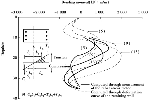
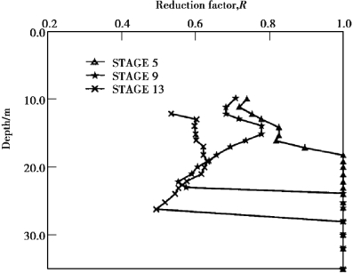
Figure 4.14 is the wall bending moments in the main observation section of the TEC excavation.The solid line refers to the bending moments obtained from the rebar strain meters embedded inside the diaphragm wall.Because the cracking of the diaphragm wall will influence the measurement results of the rebar strain meter,the computed bending moments contain the effect of cracking of the diaphragm wall.The dotted line in the figure represents the bending moment computed from the deformation curve of the diaphragm wall.The computation is as follows:First,compute the radius of the curvature by differentiating twice the multinomial function simulating the deformation curve.Assuming E is not reduced,the moment at a certain depth of the diaphragm wall can be obtained using the equation:M=El/r,where r is the radius of curvature.The bending moment computed from the wall deformation curve excludes the effect of the diaphragm wall cracking.The ratios of the bending moments from rebar strain meters to those from wall deformation curves are then the reduction factors(R),as shown in Figure 4.15.From the figure,we can see that the reduction factors at different depths are different.Basically,the reduction factors at the top and bottom of the wall are close to 1.0 and that near the excavation bottom is as low as 0.5.In analysis,we can then assign different reduction factors for different depths of the diaphragm wall.

Figure 4.14 Variations of bending moments of the diaphragm wall in the TEC excavation

Figure 4.15 Reduction factors of bending moments for the diaphragm wall in the TEC excavation
As elucidated in Section 4.2.3,column piles can be distinguished into packed⁃in⁃place(PIP)piles,reinforced concrete piles,and mixed piles.Reinforced concrete piles can further be classified into reverse circulation drill piles and all casing piles.The value of f′c for PIP piles is about 170 kg/cm2 and that for reinforced concrete piles is about 280 kg/cm2.In analysis,it can be reduced by 30%⁃50%.Which value of the reduction factor is to be taken,however,depends on the construction quality of the column pile.Besides,if considering the different degrees of cracking of concrete at different depths of the column pile,we can assign different reduction factors at different depths of the column pile,which is similar to the approach for diaphragm walls.
The value of f′c for mixed piles is about 5 kg/cm2.With rather low strength,the stiffness of mixed piles can be ignored and we can,instead,only consider the stiffness of the H steel(or W section)within mixed piles.
Affected by bending moment,the concrete of a diaphragm wall may crack and its section modulus may be thereby decreased.Thus,the section modulus in analysis is usually reduced by 20%⁃40%.According to field measurements,however,the bending moments of the diaphragm wall vary with depth and the section modulus should be reduced discriminately.Basically,the top and bottom of the diaphragm wall are the places where the reduction rate should be the lowest;whereas the wall near the excavation bottom requires the highest reduction rate.In analysis,we can assign different reduction rates for different depths.Basically,Young's moduli of sheetpiles and soldier piles are not affected by the cracking or bending moment and their section moduli are not supposed to be reduced either.If considering the repeated use of sheetpiles and soldier piles,however,reduction is still necessary.The stiffness is usually reduced by 20%.
Due to a relatively simple analytic model,simple input parameters and quick computation time,the beam on elastic foundation method has been widely used in the analysis and design of deep excavations.Because of its easier model,however,it is not readily adopted for simulations of more complicated excavations.
