4.3.3 Finite element method
Under normal excavation conditions,excavation⁃induced stress and deformation are engendered by unbalanced forces acting on the wall due to the removal of soils within the excavation zone.The magnitude of unbalanced forces is influenced by many factors:the conditions of soil layers,the table and pressures of groundwater,the excavation depth,the excavation width and so on.Theoretically,the finite element method is capable of simulating these factors and therefore the results derived from the method would be more accurate than those derived from simplified methods or the beam on elastic foundation method.The theories on which the finite element method is based,however,are rather complicated and the data to be processed both before and after analysis are enormous.What's more,some of the theories are not fully developed.To apply a program based on the finite element method,analysts are required to be well equipped with comprehensive geotechnical knowledge and experience.All this adds confusion and trouble for analysts.
Considering the complexity of the finite element method and that any small neglect is likely to lead to wrong results,the results of the finite element method should be examined by other methods,for example,the simplified methods,to ensure the reasonability of the results.
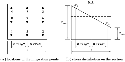
The yielding stress of the retaining wall and struts is usually very high and can be analyzed using linear elastic models.That is,Young's modulus and Poisson's ratio are assumed to be constants.Either plane strain elements or beam elements can be used for the analysis of retaining walls.If beam elements are adopted,the bending moment of the retaining wall can be found at each node of the elements.If plane strain elements are adopted instead,the bending moment of the retaining wall can be computed through the stresses at the integration points within the element.For example,a Q8 plane strain element has 9 integration points.The relative positions of the integration points are as shown in Figure 4.16(a).The finite element method can directly obtain the stresses at these 9 integration points.Figure 4.16(b)shows the typical distribution of stresses due to bending in the central section of the retaining wall.The stress includes the axial stress caused by the self⁃weight of concrete and the stress induced by the bending moment.Taking a unit width for computation,the wall bending moment(Mwall)and the flexural stress(δmax)at the outer fiber of the wall have the following relation:

where
t=thickness of the wall.
If the stresses at No.6 and 8 integration points are used to compute the wall bending moment,the aboveδmax can be computed by the following equation:

whereσ8 is the horizontal stress at No.8 integration point andσ6 is the horizontal stress at No.6 integration point.

Figure 4.16 Computation of the bending moment of the retaining wall
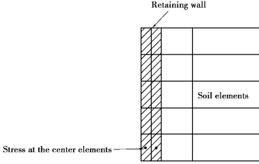
If the computer outputs do not provide the stresses at the integration points,or only provide the stresses at the center of the element,the retaining wall should then be divided into two lines(see Figure 4.17)and then we should compute bending moments through the stresses at the centers of the elements using the method above.

Figure 4.17 Double elements used for the retaining wall
