5.4 Damage to Buildings
This section considers the key principles of building damage assessment;it does not cover assessment of damage to utilities,which require very specific considerations.
Cracks are the main indicators of damage to a building.Cracks can be caused by effects such as temperature variations,moisture content changes(shrinkage),chemical reactions etc.or by deformations of the building.
Buildings located near excavations can experience several types of deformation(e.g.“sagging”or“hogging”,rigid body tilt)and can be damaged depending on their construction type,stiffness,openings and joints.The 3D behaviour of a deep excavation can reduce or increase the amount of damage suffered by nearby buildings.Where the subsidence contours are oblique to the structure,cracking occurs in the walls and floor,accompanied by diagonal cracks.When assessing actual or potential building damage,it is important to distinguish between the different deformation types.
Damage due to deformations is related to the curvature of the building.More curvature is indicative of higher strains and more damage.The most likely deformation types are“sagging”and“hogging”as described by Burland and Wroth(1974).The sides of the building settle more than the average in the“hogging”type of deformation;whereas in“sagging”the central part of the building settles most(Figure 5.14).
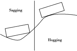
Figure 5.14 Sagging and hogging deformation modes
Rigid body tilt should not contribute to the stresses and strains in the building and causes indirect damage due to gravity forces on structural elements(such as walls).However,Leonards(1975)reported that for framed structures founded on isolated footings,tilt contributes to stress and strain in the frame,unless each footing tilts or rotates through the same angle as the overall structure,which is highly unlikely.
In the previous sections,all excavation⁃induced ground movements are considered as“greenfield”displacements,i.e.ignoring the presence of any surrounding buildings or developments.However,it is known that the presence of the building and its interface with the ground also influences the profile of the settlement and the way the displacements are transferred to the building.
Potts and Addenbrooke(1997)investigated the effect of building stiffness on tunnelling⁃induced displacements by undertaking a parametric study using finite element methods with a non⁃linear elastic⁃plastic soil model.The building was represented as an equivalent beam having bending and axial stiffness EI and EA(where E is the Young's modulus of elasticity,A is the cross⁃sectional area and I is the moment of inertia of the beam).They defined bending stiffnessρ∗and axial stiffnessα∗as

where
H is the half⁃width of the beam;
Es is representative soil stiffness.
Design curves were established for the likely modification to the Greenfield settlement profile caused by a surface structure.Franzius et al.(2004)extended the work of Potts and Addenbrooke by including the effect of building weight.Franzius et al.(2006)then discussed this further by varying the soil⁃structure interface.These effects were also investigated by EL Shafie(2008)who performed centrifuge tests on model buildings subject to excavation induced ground movements.EL Shafie(2008)concluded the following:
•The effect of building weight(up to 40 kPa)is small.
•Stiff buildings tend to tilt regardless of the soil⁃structure interface.Horizontal displacements were clearly influenced by a smooth interface,leaving the greenfield soil displacements intact,even for higher axial stiffness.Slip between the building and the soil occurred.Rough inter faces restrained the horizontal movements of the building.
•Buildings with individual spread footings experienced large differential settlements resulting in significant distortions and tensile strains concentrating at the weaker parts of the building.
Cording et al.(2010)proposed that geometry,age of construction and condition,including previous deterioration and finishes,all affect the response of the building to ground movements.So,an understanding of the structural characteristics of the building will help in determining potential distortion and damage.
A three⁃stage approach should be adopted for assessing potential damage to buildings near excavations supported by embedded retaining walls(see Figure 5.15).
Stage 1:Ground movements behind the retaining wall should be estimated as described in Section 6.3 assuming greenfield conditions,i.e.ignoring the presence of the building or utility and the ground above foundation level.Contours of ground surface movements should be drawn and a zone of influence established based on specified settlement and distortion criteria.All structures and utilities within the zone of influence should be identified.
Stage 2:A condition survey should be carried out on all structures and utilities within the zone of influence before starting work on site.The structure or utility should be assumed to follow the ground(i.e.it has negligible stiffness),so the distortions and consequently the strains in the structure or utility can be calculated.In some circumstances,a“wave”of settlement may be experienced by the structure as the settlement develops over time.The method of damage assessment should adopt the limiting tensile strain approach.See also Table 5.3,Figure 5.16 and Box 5.2.Note:
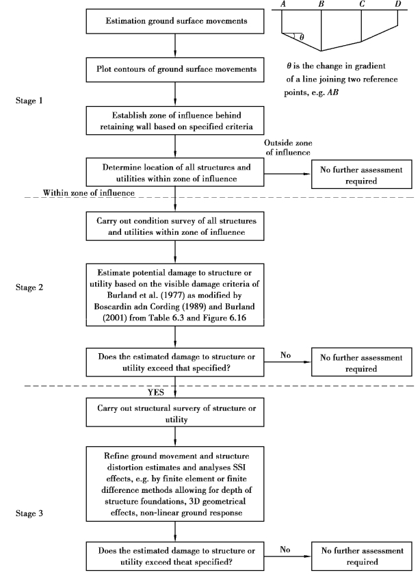
Figure 5.15 Procedure for building damage assessment
By adopting values ofεlim associated with various damage categories given in Table 5.3,figure 5.16(b)can be developed into an interaction diagram showing the relationship betweenΔ/L and εh for a particular value of L/H.Figure 5.16(c)shows such a diagram for(L/H)=1.0.
Table 5.3 Classification of visible damage to walls
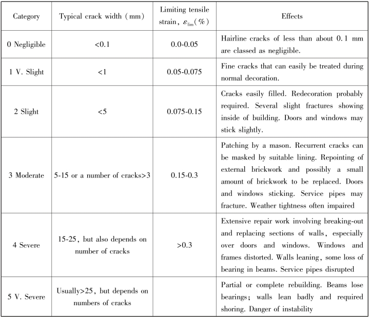
Notes:1.In assessing the degree of damage,account must be taken of its location in the building or structure.
2.Crack width is only one aspect of damage and should not be used on its own as a direct measure of it.
Reinforced concrete⁃framed structures are more flexible in shear than masonry structures and are consequently less susceptible to damage.However,for the purposes of a Stage 2 assessment of potential damage,all structures should be treated as masonry structures.
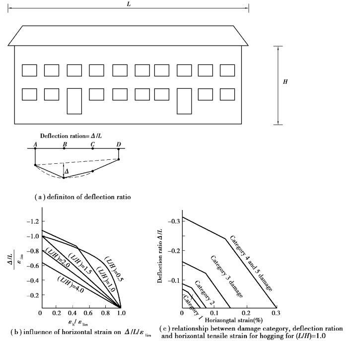
Figure 5.16 Relationship between damage category,deflection ratio and horizontal tensile strain(after Burland,2001)
Box 5.2 Procedure for stage 2 damage category assessment
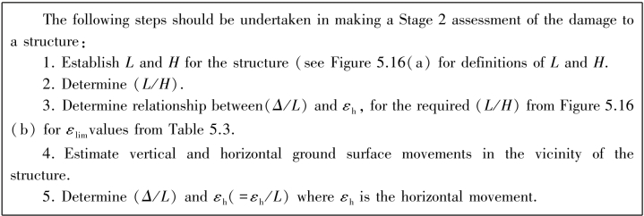
If the estimated damage category is higher than that specified,a Stage 3 assessment should be carried out.
Stage 3:A structural survey of the structure or utility should be carried out.Ground movement estimates should be refined and a SSI analysis carried out allowing for the depth of structure foundations,3D geometrical effects,non⁃linear ground characteristics and structural stiffness.The response of the structure should be assessed allowing for the actual conditions,materials and form of construction comprising the structure.The quality of workmanship in building construction can significantly affect robustness of the building and its ability to tolerate movement.
Cording et al.(2010)observed through model testing and examples that where buildings are assumed to be more flexible or at least of varying stiffness,and especially where the bays or building units are significantly narrower than the settlement profile,it may be more appropriate to consider angular distortions across individual building units.In this case,beam analysis as previously described may underestimate the actual damage level.
