12.4.3 First⁃order reliability Method
Zhang(2015a)provides a framework using spreadsheet to updating parameters,based on First⁃Order Reliability Method(FORM).
The second moment reliability indexβis defined by Hasofer and Lind(1974),and the matrix formulation(Veneziano 1974;Ditlevsen 1981)is given

where xi is random variables,μi is the mean value,R=correlation matrix,σi is standard deviation,F=failure domain.
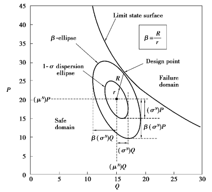
The point denoted by the xi values which minimize the square root of the quadratic form in Eq.12.50 and satisfies x∈F is the design point—the point of tangency of an expanding dispersion ellipsoid with the limit state surface which separates safe combinations of parametric values from unsafe combinations.

Figure 12.5 Equivalent dispersion ellipses and reliability index in the original space of the basic random variables(after Low and Tang,1997)
As a multivariate normal dispersion ellipsoid expands from the mean⁃value point,its expanding surfaces are contours of decreasing probability values,according to the following established probability density function of the multivariate normal distribution:

whereβis defined by Eq.12.50,without the“min”.Hence,to minimizeβin the previous multivariate normal distribution is to maximize the value of the multivariate normal probability density function,and to find the smallest dispersion ellipsoid tangent to the limit state surface is equivalent to finding the most probable failure point(the design point).
For normal variates,the design point,the first point of contact between the expanding dispersion ellipsoid and the limit state surface in Figure 12.5,is the most probable failure point with respect to the safe mean⁃value point at the centre of the expanding ellipsoid.The reliability index is the axis ratio(R/r)of the ellipse that touches the limit state surface and the standard deviation dispersion ellipse.By geometrical properties of ellipses,this codirectional axis ratio is the same along any“radial”direction.
For calculatingβin an efficient way,Low and Tang(1997,2007)developed procedures using Mircosoft Excel's Solver tool.The procedures have been widely used for geotechnical problems.
Zhang(2015a)let the limit state surface equation be the deviation between the observation and predicted response and used the spreadsheet framework to updated soil parameters.The prediction of response involves a polynomial regression model proposed by Zhang(2015b).
The model suggests the maximum wall deflectionδh as a function of seven input parameters:soil unit weightγ,excavation width B,excavation depth H,normalized soil shear strength ratio cu/σ′v,normalized soil stiffness ratio E50/cu,system stiffness in logarithmic scale ln EI/γwh4avg and soft clay thickness T,in whichσ′v is the vertical effective stress,E50 is the secant soil stiffness modulus,EI denotes the wall bending stiffness,γw is the unit weight of water,and h4avg represents the average vertical strut spacing.The equation takes the following form:

whereμw is medication factor of initial ground water table,which can be approximated as μw=1-0.1l,and l is the depth of the ground water table below the ground surface(in meters)and l≤2.
![]()
The differences,defined as g(xi),between the PR predicted maximum wall deflectionδh,PR and the field measurementδh,M for each excavation stage are minimized though g(xi)=δh,PR-δh,M under condition of where a primed dimensionless variable  is defined as
  =(xi-μxi)/σxi,in which each soil variable xi is defined in terms of its meanμxi and its standard deviationσxi.x′is the vector of the
 s and the superscript T indicates the transpose of a matrix or vector,
 is the design point which minimizes d and satisfies g(xi)=0.The problem is then a constrained minimization that can be summarized as the requirement to minimize d subject to the constraint that g(xi)=0 is satisfied.
Generally speaking,the constrained minimization can be performed through a spreadsheet or mathematical software such as MATLAB.In this study,the design point  and thus the minimal d value were obtained by using the EXCEL spreadsheet's built⁃in optimization routine SOLVER.
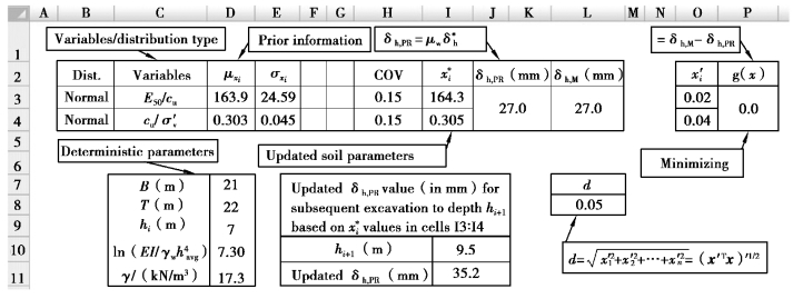
Figure 12.6 shows the example spreadsheet setup for deriving the updated soil parameters through minimizing the difference between the actual measured wall deflectionδh,M and the estimated valueδh,PR obtained using this PR model.
The spreadsheet⁃based procedure for estimating the posterior distribution can be summarized as follows:
Step 1:The semi⁃empirical PR model is firstly implemented in the spreadsheet,as shown in cells J3∶K4 in Figure 12.6.For the excavation case histories presented later,γ,B,H for each excavation stage,ln(EI/γwh ),and T are simply treated as constants since they are either deterministic geometrical properties or can be determined fairly precisely.These five constant inputs are input in cells D7∶D11.For simplicity,the distribution types of the random parameters cu/σv′ and E50/cu are assumed as normal.The prior mean and standard deviation(SD)of input parameters cu/σv′ and E50/cu are input into cells D3∶D4 and E3∶E4,respectively;the COVs for the two soil parameters are input into cells H3∶H4.Cells L3∶L4 contain the measured wall deflection corresponding to excavation to depth Hi.The x′i vector in Cells O3∶O4 contains equations for(xi-μxi)/σxi as defined for Eq.12.53.
Step 2:In this step,the posterior mean of the two input parameters are obtained by minimizing the difference betweenδh,M andδh,PR,which is input into Cells P3∶P4.The design point  value in Cells(I3∶I4)was obtained by using the EXCEL spreadsheet's built⁃in optimization routine SOLVER to minimize the cell,by changing the
  values,under the constraint that the performance function g(xi)=0.Prior to invoking the SOLVER search algorithm,the
  values were set equal to the original mean values(150,0.25)of the two variables.Iterative numerical derivatives and directional search for the design point
  are automatically carried out in the spreadsheet environment with“Automatic scaling”,“Quadratic for Estimate”,“Central for Derivatives”,and“Newton for search”set as default options.It can be observed from Figure 12.6 that,based on the measuredδh,M or 27.0 mm at an excavation depth Hi of 7.0 m and the prior mean values of(163.9,0.303)of the two soil parameters,the updated soil parameters are(164.3,0.305)and the corresponding forward prediction of the wall deflection at the subsequent stage(where Hi+1=9.5m)is 35.2 mm(CellⅠ11).
Step 3:These procedures are repeated stage by stage till the end of excavation(where H equals to the final excavation depth)and final pair of cu and E50/cu values and be determined.

Figure 12.6 Example spreadsheet for updating of soil parameters(Zhang,2015a)
A well⁃documented case history,TEC(Taipei Enterprise Center),is taken as an example of the application of this back analysis method.Table 12.4 summarizes the inputs of this case and Table 12.5 lists the measured wall deflection at each excavation stages.
Table 12.4 Initial parameters of TEC case

Table 12.5 Observed wall deflection of TEC case

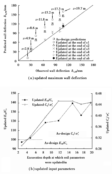
The mean values of these predictions versus the field observations were plotted in Figure 12.7,in which the predictions made prior to excavation,herein referred to as the as⁃design predictions,are denoted with the square symbol.These are the predictions made from Eq.12.53,without any field measurements and involving no updating of the soil parameters.The as⁃design predictions using the initially assumed prior information deviate from the 1∶1 line(the predicted deflections versus the observed values).Here the observed wall deflections are those measured at the end of stages 1⁃7.The predicted maximum wall deflections are those predicted prior to stages 1⁃6,respectively.It should be noted that prior to each excavation stage,the wall deflection predictions are made for various excavation depths that are anticipated at all subsequent stages.That is,prior to stage 3,predictions are made at depths corresponding to end of stages 3⁃7,respectively.It is obvious that predictions updated at the end of stages 1 and 2(s1 and s2),labeled with circle in red and triangle in blue respectively,also deviate from the 1∶1 line.As mentioned previously,back⁃analysis for the purpose of updating soil parameters is more meaningful for stage 3(s3)onwards as a result of the inevitable change of deformation patterns for s1 and s2.From stage 3 onwards,the updated predictions were very close to the 1∶1 line.The updated wall deflect at the end of stage 6 is 113 mm,much closer to the observed 108 mm,compared with the 147 mm based on the as⁃design estimation.
The updated mean values of E50/cu and cu/σ′v are shown in Figure 12.7.It is obvious that both E50/cu and cu/σ′v change as the excavation proceeds.

Figure 12.7 Updating at various excavation depths for TEC case(Zhang,2015a)
