9.4 Ground Improvement Design
The first step of ground improvement is to determine the location of improvement.Ground improvement outside an excavation zone will decrease the active earth pressure acting on the retaining wall,and within the excavation zone will increase the passive resistance of soils against the retaining wall.The ideal measure is to improve the soils both inside and outside the excavation zone.Nevertheless,the cost may be too high.
According to Ou and Wu's(1990)parametric study using the finite element method,the effects within the excavation zone are better than those outside,given the same conditions.Judged from mechanisms,once excavation is started,the retaining wall will move toward the excavation zone and the active earth pressure is thus produced no matter whether the soils outside the excavation have been improved or not.Therefore,the earth pressure acting on the retaining wall will not be decreased too much.On the other hand,the ground improvement inside the excavation zone will always directly restrain the movement of the retaining wall.Obviously,the effects of ground improvement inside the excavation zone are better than improvement outside.
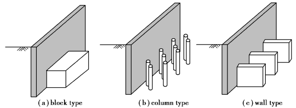
The location determined,it follows to determine the arrangement of improvement.To resist the forward movement of the retaining wall,some commonly used arrangements include the block type,the column type,and the wall type,as shown in Figure 9.6.The arrangements of these types are elucidated as follows:
①Block type.Within a specific area,improve the soils fully.Replace the soil bodies within the area completely or have them completely combined with chemicals into treated soils.

Figure 9.6 Typical arrangement of soil improvement in excavations
②Column type.The pattern of the improved soils is similar to that of piles.The columns of improved soils do not connect with each other.
③Wall type.Connect the columns of improved soils into a wall shape,which joins the retaining wall and forms a counterfort⁃like wall.The wall can only increase the soil strength in front of the retaining wall.It is not able to raise the moment⁃resistance stiffness of the wall.
When block type and wall type are adopted,the location of grouting holes should also be arranged according to effective range of grouting to form a continuous grouting body.
①Single row:as shown in Figure 9.7,let l be grouting hole distance,and r be effective radius of grouting,then the effective width of grouting body b is

Figure 9.7 Design of a single row grouting
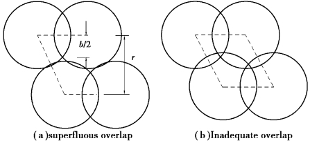
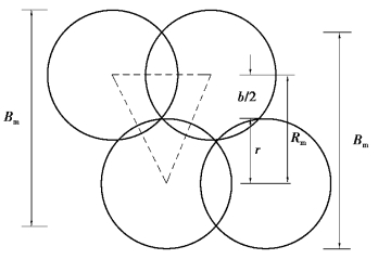
②Multiple rows:if a single row cannot meet the required effect width,multiple rows arrangement should be employed.To maximize utilization of grouting,both superfluous[Figure 9.8(a)]and inadequate overlap[Figure 9.8(b)]are supposed be avoided.The optimal arrangement is shown in Figure 9.9,and the optimal row distance rm and effective width bm are

Figure 9.8 Design of double rows grouting

For double rows:

For triple rows:

Drawing from the above elucidation,for odd number rows:

For even number rows:

where N is the number of rows.

Figure 9.9 Optimal overlap among grouting
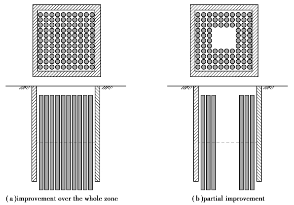
Figure 9.10 diagrams the plan and profile of the column type of ground improvement.Under such a condition,the passive resistance can be computed on the basis of the properties of the treated soils(composite soils).Both whole[Figure 9.10(a)]and partial[Figure 9.10(b)]improvement within the excavation zone is used,though the passive resistance of soils against the retaining wall under the former condition will be smaller than the latter.
To ensure ground improvement capable of property protection,improvement should be analyzed in terms of the strength of the treated soil,its diameter,span,depth,location,and range.The soils within the area can be viewed as a composite material in analysis.When the composite soil body bears load,according to the principle of force equilibrium,the strength of the composite soil can be written as

Figure 9.10 Soil improvement within excavation zone
![]()
where
 t=shear strength of the treated soil;
 s=shear strength of the untreated soil;
m=improvement ratio,that is,the area of the treated soil divided by the total area.
