8.6 Dewatering and Ground Settlement
Dewatering will decrease the porewater pressure and increase the effective stress of soils accordingly.In sandy or gravelly soils,the increase of effective stress will produce elastic settlement.In clayey soils,not only elastic settlement but consolidation settlement will be induced.Generally speaking,the amount of elastic settlement is far less than that of consolidation settlement and usually can be neglected.As far as dewatering and pumping are concerned,the consolidation settlement should be considered.
The amount of consolidation settlement induced by pumping can be computed by using Terzaghi's one⁃dimensional consolidation theory as follows:
For normally consolidated clay:

For overconsolidated clay:

where
δ
v=consolidation settlement;
H=thickness of the clay;
e0=initial void ratio;
Cc=coefficient of compressibility;
Cs=the coefficient of swelling;
σ′v0=vertical effective overburden pressure in the clay;
σ′p=preconsolidation pressure;
Δσ=the increment of vertical effective pressure caused by pumping.
Whether dewatering or pumping will cause settlement relates to the locations of wells,the depths and the drawdowns(see Figure 8.21).
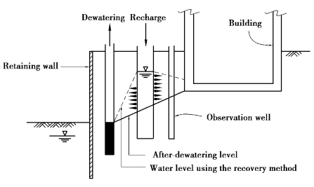
Figure 8.21 Recovery method
Theoretically,the influence range of dewatering⁃induced settlement is the distance from which settlement declines to 0.However,the definition has little meaning in engineering practice.As explicated,drawdown is the major cause of settlement.If we apply Theis's nonequilibrium theory to compute the influence range of drawdown,the range will work out as extremely far.The result of Jacob's modified nonequilibrium equation is similar.Does it follow that the influence range of settlement is actually extremely far?Certainly not.Thus,the reasonable settlement influence range should be determined on condition thatδ=δa(δa is the allowable settlement)or when the angular distortion is small.
(1)Example 8.1
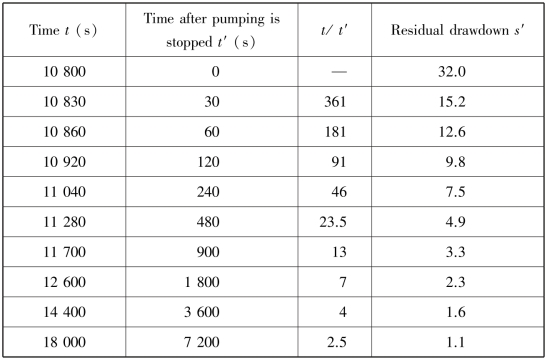
The allocation of the pumping wells and observation wells are shown in Figure 8.22.The thickness of the permeable layer is 10 m;the distances between the pumping well center and the observation wells K⁃1,K⁃2,and K⁃3 are 10,20,and 30 m,respectively.The radius of the well rw=0.5 m;the punmping rate Q=2 000 cm2/s.Table 8.4 lists the drawdowns observed in the pumping well and the three observation wells.Table 8.5 lists the recovered water levels after pumping is stopped.Compute the coefficients of transmissivity and storage using the methods of Theis,Jacob,and Thiem,and the recovery method,respectively.
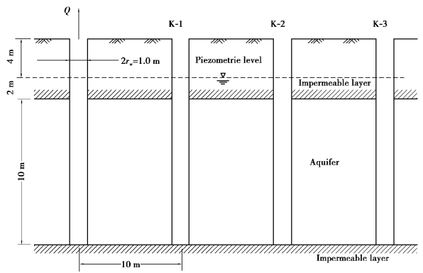
Figure 8.22 Pumping test and the soil condition
Table 8.4 Results of the pumping test
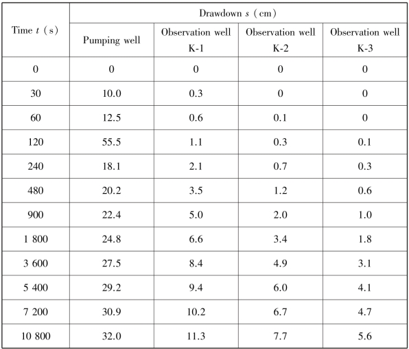
Table 8.5 Recovered water levels in the pumping well
(2)Theis's nonequilibrium euation
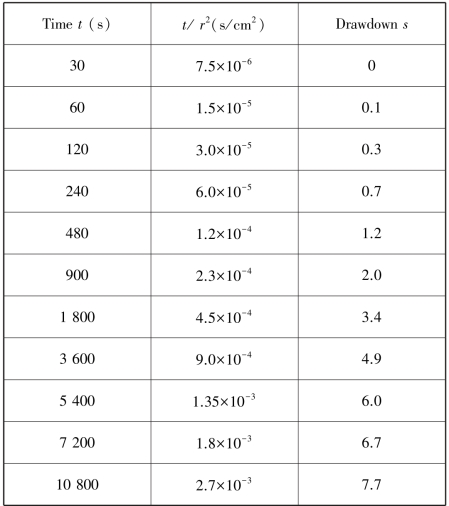
Let K⁃2 be the object of analysis and t the variable,compute the s⁃t/r2 relation as shown in Table 8.6.Depict the standard and data curves and superimpose one onto the other.As shown in Figure 8.23,we have the coordinates of the match point:
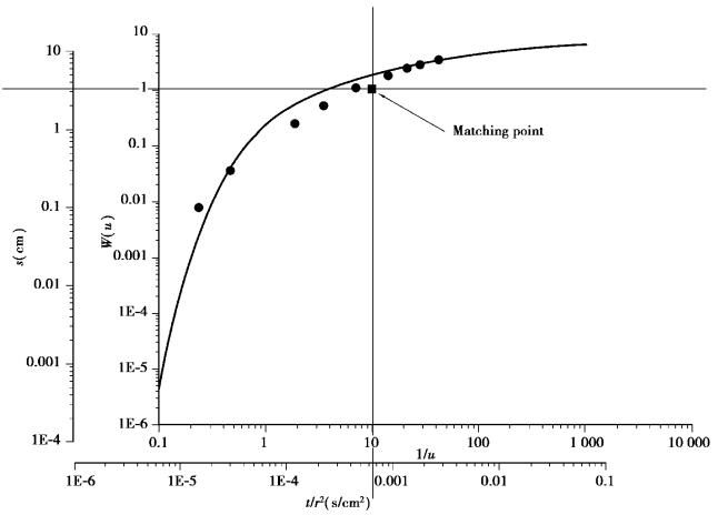
Figure 8.23 Matching point in theis's method
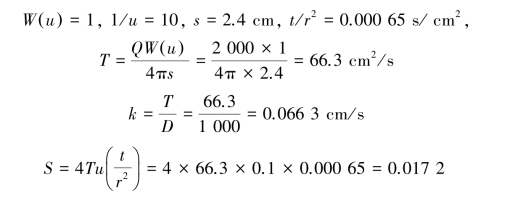
The readers could try deducing the procedure using r as a variable at a specific time t,and the result is not unique but similar.
Table 8.6 Computation based on time as variable
(3)Jacob's modified nonequilibrium equation
Jacob's modified nonequilibrium equation also has two ways to analyze:use either t or r as the variable.Using t as the variable,the computation is as follows:according to the data of K⁃2,plot s-log t/r2 relation is as shown in Figure 8.24,where we have(Δs)J=5.61 cm and(t/r2)s=0=0.000 12 s/cm2.
then


The readers could try deducing the procedure using r as a variable at a specific time t.
(4)Thiem's equilibrium equation
Assume all wells reach equilibrium when t=10 800 s,from Table 8.2,depict the s⁃log r curve as shown in Figure 8.25 where we have(Δs)T,the s decreases to marginal when r incresses by ten times,equal to 12.1 cm.That is to say,when log r1/r2=1.0,s1-s2=∗12.1 cm,then

The coefficient of transmissivity can be derived from T=kD,or find R on the Figure 8.25 R=87 m.

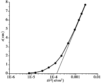
Figure 8.24 Jacob's method
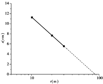
Figure 8.25 Thiem's method
(5)The recovery method
According to the data in Table 9.3,plot s′-log(t/t2)curve as shown in Figure 8.26 where we obtain(Δs′)r=8.5 cm.

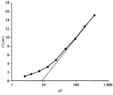
Figure 8.26 The recovery method
(6)Example 8.2
According to the analysis results of Theis's method in Example 8.1,estimate the required total quantity of water to be pumped in Figure 8.27.
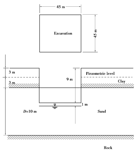
Figure 8.27 Plan and profile of an excavation
From Example 8.1,we know

Using the method of the equivalent area,compute the radius of the imaginary well as follows:

The excavation depth is 9 m.The groundwater level is to be lowered to 1 m below the excavation surface.As a result,the drawdown s=7 m.Assume the pumping time t=15 days=21 600 min.Then,the well parameter is

with u<0.01,we can use Jacob's nonequilibrium equation:
W(u)=-0.577 2-ln u=7.46
and the required quantity of water to be pumped is

(7)Example 8.3
The thickness of a sandy soil layer is about 40 m,below which is an impermeable rocky stratum.The groundwater level is at the ground surface.The coefficient of permeability of the sandy layer is 2.0×10⁻³ cm/s;the coefficient of storage is 0.2.Here is an excavation site of 100 m×50 m;the excavation depth is 8.5 m.For the convenience of excavation and restricted time of construction,the well point method is to be adopted to lower the groundwater level to 1.0 m below the excavation surface within 15 days.Design the numbers of the well points.
To lower the groundwater level by 9 m within 15 days may leave the drawdown in the nonequilibrium condition.Thus,a nonequilibrium equation is to be adopted for analyses.With the drawdown within the excavation zone to be 9.5 m,which is far less than the thickness of the aquifer,we can choose either Theis's or Jacob's nonequilibrium equation.The circumference of 100 m×50 m can be converted to an equivalent radius of

The well parameter

With the pumping height limited to about 5 m for well points and the required amount of dewatering about 9 m,dewatering has to be carried out in two phases:
Assume the discharge quantity of each well point Qw=0.01 m3/min.The dewatering height of the first phase s=5 m(water level lowered from GL0.0 to GL-5.0 m).The required quanitiy of water to be pumped will be
![]()
and the required number of well points will be

Assume the collecting pipes are arranged along the two longer sides of the excavation site,which is 200 m long in total.The distance between two well points will be

The dewatering height of the second phases=4.5 m(the groundwater level lowered from GL⁃5to GL⁃9 m).A possible drawdown curve is also as shown in Figure 8.12.The quantity of water to be pumped will be

Assume the collecting pipes are also arranged along the two longer sides of the excavation site.The distance between two well points will be

