6.2 Basic Principles
This section explains the basic principles of the finite element method.In an excavation,find a section,the central section in most cases,whose behaviors meet the plane strain condition as shown in Figure 6.1(a).Take the profile of this section and divide the soils and structures within the excavation influence range into many meshes,each of which is called an element[see Figure 6.1(b)].According to the properties of the material of each element,establish its stress⁃strain relation,which is called the constitutive law.The constitutive law of an isotropic material can be expressed as follows:
![]()
where
{σ}=stress matrix.The sign{}refers to a column matrix;
{ε}=stram matrix;
[C]=stress⁃strain relational matrix.
Under the condition of plane strain,the matrices are
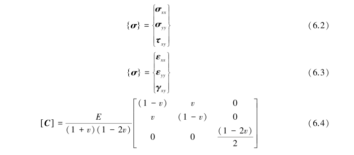
E and v in Eq.6.4 are Young's modulus and Poisson's ratio,respectively.
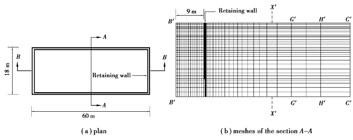
Figure 6.1 Finite element analysis of an excavation
As shown in Figure 6.2,the relation between the displacement at any point within the element and that of the nodal point of the element can be expressed as follows:
![]()
where[f]=displacement shape function.
According to the theory of elasticity,the strain and displacement at a point within the element have a relation which can be expressed as follows:
![]()
where[d]=linear partial differential operator,such as ,
, ;[B]=[d][f]=relational matrix between the strain and the nodal displacement.
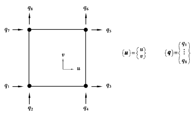
Figure 6.2 Four⁃node element
According to the principle of virtual work,we can derive the stiffness matrix of the element to be

After establishing the relational matrices for all the elements,combine them into the global stiffness matrix[K].Then compute the excavation⁃or load⁃induced external forces,which are then transformed into the external force of the nodal points.The following equation can then be established:

where
{q}=nodal displacement matrix.
[K]=global stiffness matrix.
{P}=matrix of excavation⁃induced external force or equivalent nodal load at nodal points.
The nodal displacement{q}can then be solved with Gauss elimination method or other numerical methods.Using Eq.6.5,we can then obtain the displacement at any point within the element.By means of Eq.6.6,the strain at any point within the element can be obtained.Lastly,use Eq.6.1 for obtaining the stresses at any point within the element.As a result,we can obtain the deformation,the stress,the strain,the bending moment of the retaining wall,the ground surface settlement,and the movement of the excavation bottom.
When the displacement shape function[f]is quadratic,differentiated by the partial differencial operator[d],the matrix[B]becomes linear,which shows that the strain within the element changes linearly.The element within which the strain changes linearly is called the low order element.Otherwise,those within which strains do not change linearly are called high order elements.
Since the order of the shape functions of high order elements is higher than those of the low order elements,the number of nodes of high order elements is larger than that of low order elements.High order elements are more capable of coping with the rapid change of stress or strain within an element and are thereby more accurate than low order elements.
The commonly used deformation parameters,in addition to E and v in[C]in Eq.6.4,can also be represented by the shear modulus G,the bulk modulus B,and the constrained modulus M.Their definitions are shown in Figure 6.3 and explained as follows:
As shown in Figure 6.3(a),under the compressive force,E and v are separately defined as

Figure 6.3(b)shows the strainsε1,ε2 andε3 produced under the action of the stresses,σ1,σ2andσ3.Thus,the bulk modulus is

where
εv=volumetric strain= ≈ε1+ε2+ε3;
ΔV=change of the volume;
V=volume.
Figure 6.3(c)shows the shear strain produced under the action of the shear stress, .Thus,the shear modulus is whereγ=shear strain.

Figure 6.3(d)displays the axial load,σ1,on the material while the lateral strain is restrained.That is,the lateral strain is 0.The constrained modulus is

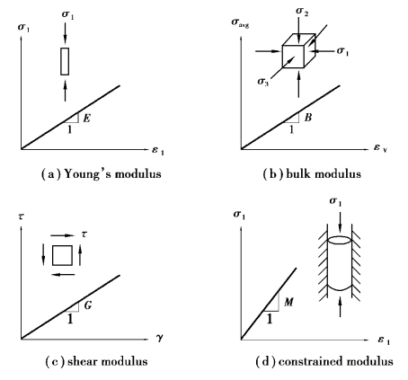
Figure 6.3 Definitions of various deformation moduli
According to the theory of elasticity,the relationship between the deformation parameters E,v,G,B,and M can be derived,as shown in Table 6.1.That is,[C]in Eq.6.4 can also be expressed by any two parameters among E,v,G,B,and M.Thereby,the matrix[C]in Eq.6.4 is also often expressed in G and B as follows:

Table 6.1 Relations between elastic deformation parameters(After Chen and Saleeb,1982)
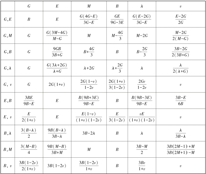
Note:λis a Lame parameter.For its definition,please see books on theory of elasticity.It is,though,rarely used in geotechnical analyses.
In the plane strain excavation analysis,the commonly used elements can be categorized into the plane strain elements,the bar elements,and the beam elements,etc.
