11.3.1 Lateral deformation of retaining walls and ...
The lateral deformation of a retaining wall(such as soldier piles,diaphragm wall)is one of the important monitoring items of excavation.The lateral deformation of a retaining wall relates closely to the ground settlement(or the settlement of the buildings).The magnitude and shape of lateral deformation of the retaining wall can be used for the judgment of the safety of the retaining wall or the buildings in the vicinity.
To explore the characteristics of an excavation or for some special objectives,it is sometimes required to measure the lateral deformation of soils.The strain at a specific point in the soil can be computed if extensometers,used to measure vertical movement at a point in the soil,are installed near an inclinometer casing.The results can be used to understand the tendency to movement of soil.This data is important for excavation studies though difficult to apply to the judgment of excavation safety.
The inclinometer casing and the inclinometer are commonly used devices for the measurement of the lateral deformation of retaining walls or soils.An inclinometer casing has four tracks,which constitute the two perpendicular axes,along each of which two sets of wheels of inclinometer are embedded.The two ends of an inclinometer casing are the male and female joints(Figure 11.1),respectively,by which several inclinometers can be connected to measure greater depth.The spiral of an inclinometer casing should be as small as possible.Otherwise,the tracks may not be on a vertical plane.This is a factor influencing the precision of measurement.ABS(acrylonitrile/butadiene/styrene)pipes,PVC pipes and aluminum pipes are commonly used materials for inclinometer casings.Aluminum and PVC pipes are usually formed through injection molding.As a result,the measuring tracks are external to the piles[Figure 11.1(a)].In ABS ones,however,four tracks are hollowed in the pipes using lathes[Figure 11.1(b)].
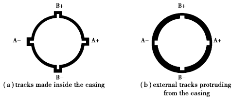
Figure 11.1 Inclinometer casings
Fig 11.2 illustrates the photo and basic configuration of an inclinometer.As shown,the inclinometer is a four foot(two pairs of wheels)instrument containing a tilt measuring sensor(also called an electronic pendulum).The top of the inclinometer is connected to a cable,which is,in turn,connected to a readout on the ground surface.According to the type of measuring unit of the sensor,the inclinometer can be divided into resistance type,vibrating types,and force balance accelerometer type.The force balance accelerometer type places a pendulum amid the magnetic field of coils of a location detector.When a tilt is produced,the coil magnetic field of the location detector can then detect the displacement of the pendulum with respect to the vertical line.The signal is then converted into a voltage by the detector.The voltage going through the coil will generate a force to have the pendulum recover its original place.Have the measured voltage converted and we can then get the tilt angle.
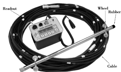
Figure 11.2 An inclinometer
When installing an inclinometer casing,one pair of tracks of the inclinometer casing should parallel the direction of deformation of the retaining wall,in other words,should be perpendicular to the retaining wall.The pair of tracks perpendicular to the retaining wall is usually called the AA axis.The other pair paralleling the retaining wall is called the BB axis,as shown in Figure 11.3.
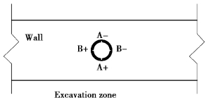
Figure 11.3 Installation of inclinometer casings with diaphragm walls
As shown in Figure 11.4,assuming the distance between the two points(or two wheels)is L and the tilt angle measured by an inclinometer isθ,the relative horizontal distance between the two points(ortwo wheels)is L sinθ.If the tilt angles taken from three serial measurements by the inclinometer areθ1,θ2,θ3,the relative horizontal distance between points A and B is∑L sinθ=L sinθ1+L sinθ2+L sinθ3.
As discussed above,the value taken from an inclinometer is the relative horizontal displacement between two points.To obtain the real displacement curve,an adjustment of the displacement of the top end of the inclinometer casing must be made or the bottom end of the inclinometer has to be placed at a real fixed point,such as a point in rocks or cobble⁃gravelly soils.Alternatively,displacement at the top of the casing can be measured using a tape,level,or theodolite against a datum line drawn before excavation.Then,as shown in Figure 11.5,suppose the displacement of the casing top measured using an inclinometer is d2.The amount of d2 is the displacement of the casing top relative to the bottom.If we move the curve laterally by(d1-d2),we can obtain the real displacement curve.
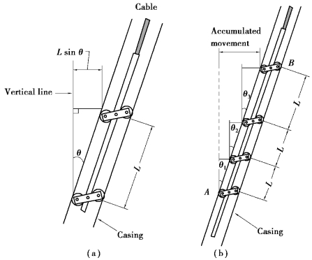
Figure 11.4 Principle of the measuring of lateral movement by an inclinometer
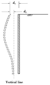
Figure 11.5 Modification of movement of the top end of casings
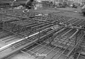
Figure 11.6 Inclinometer casings in a diaphragm wall
In case of diaphragm walls,the inclinometer casing can be fixed on a main reinforcement of the steel cage of the diaphragm wall,which is then placed in the trench and cast with concrete using Tremie pipes.This finishes the installation of the inclinometer casing,as shown in Figure 11.6.The inclinometer thus installed will not be embedded deeper than the bottom of the wall.Another way to install the inclinometer casing in the diaphragm wall,as shown in Figure 11.7,is to fix a PVC pipe with 5⁃10 mm thick walls onto a main reinforcement of the steel cage;the PVC pipe is then lowered into the trench with the cage.When casting the trench,the placement of the PVC pipe is completed.The PVC pipe is then used as a drill guide,allowing a drill to reach the hard soil.The inclinometer casing is then inserted in the PVC pipe or the bore.The space between the inclinometer casing and the bore is filled by suitable filling materials whose properties are similar to the material there.The filling materials in diaphragm wall or hard soil can be cement grouts whereas those in soils should be a mixture of bentonite and cement.
For sheetpiles or soldier piles,which the inclinometer casing is not easily fixed directly on,the inclinometer casing can also be placed in the soils within 2 m of the outer side of the wall to measure the lateral displacement because the movement of the soils near the retaining wall is quite close to that of the wall(Ou et al.,1998),as shown in Figure 11.8.
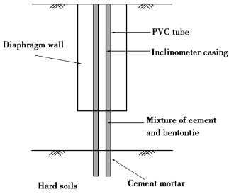
Figure 11.7 Schematic diagram of installation of the inclinometer casing in a diaphragm wall
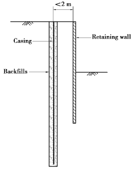
Figure 11.8 An inclinometer casing outside of the diaphragm wall
