3.2.3 Apparent pressure diagrams(APD)
The empirical methods of Terzaghi and Peck(1967)and Peck(1969a)were obtained from field measurements of strut loads and are envelopes of the maximum measured pressures.They are considered to give conservative estimates of earth pressures and provide estimates of the maximum strut loads for design purposes.They are not the actual pressure distributions but correspond to the maximum values expected.These pressure envelopes are commonly referred to as apparent pressure diagrams(APD).Figure 3.5 illustrates the procedure of calculating the apparent earth pressure(by method of Tributary Areas).That is,the load on the struts can be approximately determined by the method of tributary areas(Terzaghi,Peck&Mesri,1996),which consists in dividing in sections the pressure acting on the diaphragm wall.The division of these sections is performed in the middle of the distance between the struts,assigning the pressure value of each section to the strut that is in that section.As shown in Figure 3.5.The horizontal distance between struts here is considered to be a constant as b.From this way,strut load Q can also be calculated easily.
Figure 3.6 shows diagrams of the apparent earth pressure established by Peck(1969b).As shown in the figure,when the soil in back of the wall mainly consists of sandy soils,the apparent earth pressure Pa will be
![]()
where
γ=unit weight of sandy soils;
He=excavation depth;
Ka=Rankine's coefficient of earth pressure=tan(45°-φ/2).
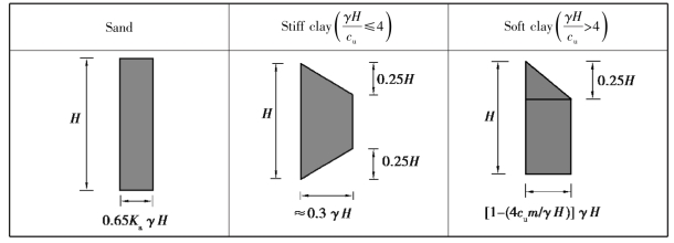
Figure 3.6 Diagrams of the apparent earth pressure(Peck,1969a)
If the soil in back of the wall is stiff clay(γH/cu≤4),the apparent earth pressure Pa would be
![]()
If the soil in back of the wall is soft to medium soft clay(i.e.γH/cu>4),the apparent earth pressure,Pa,would be the larger of
![]()
where
cu=undrained shear strength of soil within the range of the excavation depth;
m=an empirical coefficient,for deep deposit of soft clay,use m=0.4;otherwise use m=1.
In addition to Peck's diagrams of the apparent earth pressure,Terzaghi,and Peck(1967),and many other investigators have also recommended similar types of diagrams,such as the DPL(distributed prop load)proposed in CIRIA C517(Twine&Roscoe,1999),in which the classification of ground types and diagrams of different classes of soil are shown in Table 3.1 and Figure 3.7,respectively.The proposed DPL is based on 81 cases in history and field measurements of prop loads;however,of the 81 cases,28 are for flexible walls in soft to medium clays(denoted as class AF)while only 2 cases are for stiff walls(class AS).In addition,although there are 10 reported cases for stiff walls in stiff clays(class BS),5 of them are singly propped while 2 cases have two strut levels;only the remaining 3 cases have three levels of struts.At present,Peck's diagrams of apparent earth pressures are the most commonly applied in engineering design,though.
Table 3.1 Classification of ground types

From the above discussion,we can see that the apparent earth pressure is the earth pressure derived from the strut load rather than from the true earth pressure.Thus,the apparent earth pressure is only used to calculate the strut load.Though some engineers adopt the apparent earth pressure for the calculation of the stress/bending moment of the retaining wall,it is incorrect.
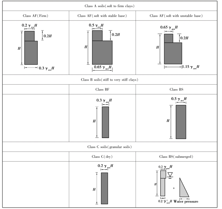
Figure 3.7 DPL of different classes of soil(Twine&Roscoe,1999)
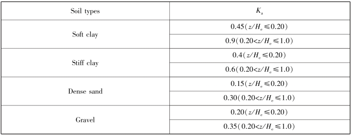
According to many documents and experience,nevertheless,the apparent earth pressure method is still useful for excavations not deeper than 10 m.As for deep excavations(over 20 m),the applicability of the method needs more examination.Recently,based on numerical studies as well as field measurements from a number of reported case histories,Goh et al.(2017)and Zhang et al.(2019)proposed updated empirical charts for determining strut loads for excavations in stiff wall systems,as shown in Table 3.2,which could be more practical in designing process of retaining structures.
Table 3.2 Recommended Ka values for stiff walls(Goh et al.2017 and Zhang et al.2019)
Example 3.1
In Figure 3.8 are the excavation profile and geological profile of a building.The excavation depth was 14.1 m.Four levels of struts were installed.The subsurface soils at the site consisted mainly of clayey soils.The groundwater level was 3 m below the ground surface.Compute the strut load following Peck's apparent earth pressure method.
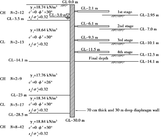
Figure 3.8 Soil and excavation profile of Building Q in Taipei
Solution
Suppose the soil above the excavation surface was clay whose normalized undrained shear strength is su/σ′v=0.32.The average unit weight of soil isγ=18.64 kN/m.We can compute the undrained shear strength at the depth of 7.05 m(14.1 m/2)below the ground surface as follows:

The soil at the site can then be categorized as soft to medium soft clay according to Peck's apparent earth pressure diagrams.The influence depth of excavation can be defined to be as deep as the excavation width.Since the excavation width B=28.8 m,the influence depth is about from the excavation surface down to 14.1+28.8=42.9 m below it.Then the stress in the soil at a depth of 28.5 m(14.1+28.8/2)is
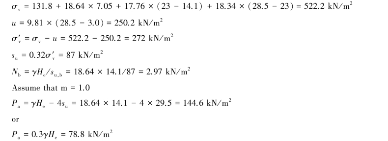
The apparent earth pressure is Pa=144.6 kN/m.The distribution of earth pressure is as shown in Figure 3.9.According to the half method,the load on each level of struts would be
The load on the 1st level of struts=144.6×3.5/2+144.6×(2+2.1-3.5)=339.8 kN/m
The load on the 2nd level of struts=144.6×(4.0/2+3.2/2)=520.6 kN/m
The load on the 3rd level of struts=144.6×(3.2/2+2.2/2)=390.4 kN/m
The load on the 4th level of struts=144.6×(2.2/2+2.6/2)=347 kN/m
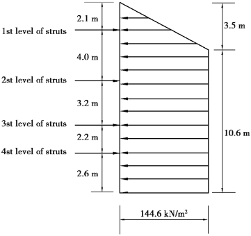
Figure 3.9 Distribution of apparent earth pressure and locations of struts
